What Is an Exploded View Drawing?
An exploded view drawing is a technical illustration that shows the components of a product separated in space along a common axis, so the viewer can see every part, its orientation, and the order in which the parts fit together.
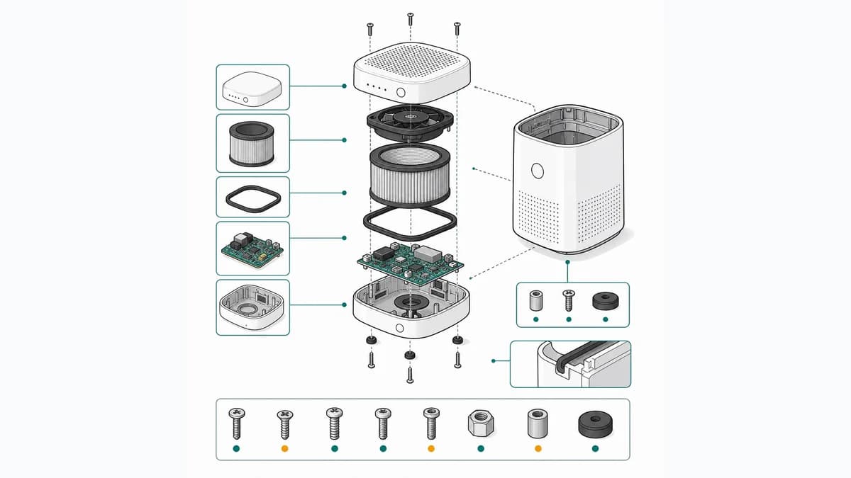
Key elements of an exploded view drawing
A well-made exploded view follows a few strict conventions. Parts are displaced along one or more explosion axes — usually the axis of assembly — and thin axis lines (also called trails or flow lines) connect each part back to its assembled position, so the drawing reads as a frozen moment of assembly rather than a random scatter of components.
Each part carries an item number inside a bubble callout (a balloon), and those numbers cross-reference a parts list or bill of materials (BOM) that gives the part name, part number, and quantity. Fasteners such as screws and washers are drawn in line with the holes they enter, which lets readers infer assembly order without any text.
When to use an exploded view
Exploded views are the standard figure type whenever readers need to understand how parts relate: assembly instructions for furniture and consumer products, spare-parts catalogs and service manuals, repair guides, patent drawings, and packaging inserts. They are especially useful when a product has internal parts that a normal photo or assembled drawing would hide.
For a single-step task, a simple before/after illustration is often clearer. Exploded views earn their place when the reader must identify many parts at once or order replacement components. They also double as reference art elsewhere in a document: the parts-identification page at the front of most furniture manuals is simply an exploded view with quantity labels.
How exploded view drawings are produced
Traditionally, exploded views are created in CAD software by defining an "explode state" for an assembly model, or drawn by hand by technical illustrators following standards for line weight and axonometric projection. Both routes require either CAD source files or significant illustration skill.
AI illustration tools now offer a third route: they can generate an exploded-style line drawing directly from product photos, which teams then refine and label. This is fastest for products without clean CAD data, such as sourced or legacy hardware.
Frequently asked questions
What is the difference between an exploded view and an assembly drawing?
An assembly drawing shows the product with parts in their final assembled positions, while an exploded view separates the parts along an axis to reveal how they fit together. Many manuals use both: an exploded view to identify parts and an assembly drawing to show the finished result.
Do exploded view drawings need to be to scale?
No. Exploded views prioritize clarity over dimensional accuracy. Parts keep roughly proportional sizes so they are recognizable, but the spacing between parts is exaggerated on purpose, and small parts like screws are often enlarged slightly so callouts stay legible.
What software is used to make exploded views?
Common options include CAD packages (SolidWorks, Fusion 360, Creo) that explode 3D assemblies, vector tools like Adobe Illustrator for hand-drawn work, and AI-based generators that create exploded-style illustrations from product photos.
Create exploded view illustrations from a photo
ManualFig turns product photos into clean, manual-ready exploded view line drawings — no CAD files or illustration skills required.
Try the exploded view generator