What Is an Assembly Drawing?
An assembly drawing is a technical drawing that shows how individual components fit together to form a complete product or sub-assembly, typically annotated with item balloons that reference a parts list or bill of materials.
Types of assembly drawings
Engineering practice distinguishes several kinds. A general assembly (GA) drawing shows the complete product with every major component in its final position. Sub-assembly drawings document one module — a gearbox, a drawer slide — that is built separately before final assembly. Exploded assembly drawings pull the parts apart along an axis to show assembly order, and installation drawings show how the finished product mounts into its surroundings.
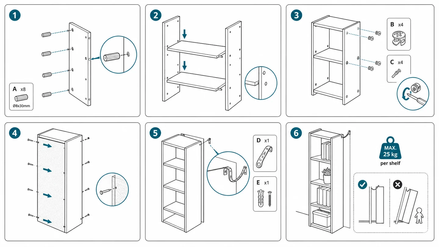
Consumer-facing assembly instructions (the IKEA-style booklet) are a simplified descendant of these engineering drawings: they keep the item balloons and step logic but drop dimensions and tolerances.
Key elements of an assembly drawing
The core elements are consistent across industries: numbered item balloons pointing at each component, a parts list or BOM table cross-referencing those numbers with part names and quantities, and enough views (or section cuts) to make every part visible. Fasteners are identified by standard designations, and orientation cues — arrows, alignment marks, centerlines — prevent parts being installed backwards.
Unlike a detail drawing, an assembly drawing rarely carries full dimensions. It answers "what goes where", not "how big is this part".
When assembly drawings are used and how they are made
Assembly drawings appear wherever something must be put together or taken apart: manufacturing floors, furniture and toy instructions, appliance manuals, and service documentation. In manufacturing they are controlled engineering documents; in consumer products they become the illustrated steps of the manual.
They are traditionally produced from CAD assemblies or by technical illustrators. For teams without CAD data — common with sourced products — AI tools can now generate assembly-style line drawings from photos of the actual parts, which writers then annotate with balloons and step numbers.
A practical rule of thumb for instructions: one drawing per assembly step, showing only the parts involved in that step plus enough of the surrounding structure for orientation. Cramming an entire product into a single drawing forces readers to hunt for the relevant parts, and that hunting is where assembly errors start.
Frequently asked questions
What is the difference between an assembly drawing and a detail drawing?
A detail drawing fully defines a single part — dimensions, tolerances, material — so it can be manufactured. An assembly drawing shows how multiple finished parts fit together and identifies them, usually without full dimensions.
What does an assembly drawing include?
Typically: one or more views of the assembled product, numbered item balloons on each component, a parts list or BOM giving names and quantities, fastener callouts, and orientation or alignment cues. Exploded views and section views are added when internal parts would otherwise be hidden.
Generate assembly instruction illustrations
ManualFig converts photos of your product and parts into clean assembly illustrations — step figures, exploded views, and part callouts included.
Try the assembly illustration generator