LogoManualFig.ai
  • 开始生成
  • 工具
  • 博客
  • 价格
How to Create Assembly Instructions (Step by Step, With Examples)
2026/07/16

How to Create Assembly Instructions (Step by Step, With Examples)

A practical, step-by-step process for creating assembly instructions from product photos — panel anatomy, wordless IKEA-style layouts, examples, and common mistakes.

A customer opens the box, tips out a flat-pack shelf, and finds the instructions for assembly: one photocopied page, a paragraph of text per step, and a single photo of the finished unit. Twenty minutes later the cam locks are in backwards, the back panel is on the front, and the one-star review is already half written — "impossible to assemble." The product is fine. The document failed.

Assembly instructions are the highest-leverage page most product companies ship. They are read at the worst possible moment — hands full, patience short, parts everywhere — and they are judged instantly. The good news is that strong assembly guides follow a repeatable structure, and with current tools you can build one from nothing more than product photos. This guide walks through the whole process: why instructions fail, the seven steps to create them, what a good panel actually contains, how wordless instructions work, and three concrete examples you can copy.

Turn product photos into numbered step panels with the Assembly Instruction Illustration Generator — no CAD file needed.

Why assembly instructions fail

Before building a good assembly instruction manual, it is worth naming exactly how bad ones go wrong, because every failure below is a design decision you can reverse:

  • Text where a figure belongs. "Insert dowel B into pre-drilled hole 4 on panel C while ensuring the finished edge faces outward" is four decisions buried in one sentence. A drawing with an arrow makes the same point in half a second.
  • Photos instead of drawings. A photo of a brown part against a brown table hides edges, holes, and orientation. Manuals use line art for a reason: it strips away everything except shape and connection. This is the same logic behind an assembly drawing in engineering documentation — show structure, hide noise.
  • Several actions crammed into one step. If step 3 says "attach the legs, insert the shelf pins, and mount the crossbar," the reader will do them in the wrong order or skip one.
  • No parts identification up front. When four screws look alike and only one is right, the reader guesses. Guesses strip threads.
  • Wrong-orientation traps left unmarked. Any part that can be installed 180° wrong will be, unless the drawing flags the asymmetry.
  • The finished-product photo standing in for every step. The reader needs the state of the assembly at this step, not the destination.

Almost every support ticket, damaged part, and "missing screws" complaint traces back to one of these. The process below is built to prevent them.

How to create assembly instructions in 7 steps

Traditional technical illustration tools assume you have a 3D CAD model to explode and annotate. Most teams that actually write the manual — product managers, e-commerce sellers, technical writers, small manufacturers — do not have the CAD file, or have one the supplier will not share. The photo-based workflow removes that dependency entirely. Here is the process, end to end.

Step 1: Assemble the product yourself and log every action

Build the product once, slowly, and write down each discrete physical action as you perform it: place, insert, align, tighten, flip, check. Note where you hesitated — every hesitation is a future customer's phone call. This raw action log is the skeleton of the manual, and it usually contains twice as many actions as you expected.

Step 2: Photograph each stage

Photograph the parts laid out, then the assembly at every stage from a consistent three-quarter angle. These photos will not appear in the manual; they are the reference inputs for the illustrations. You do not need studio lighting — you need clear part separation, the fastener visible, and the orientation unambiguous. This is the step where the photo-based approach diverges from CAD-based tools: competitors like SOLIDWORKS Composer or Cadasio need the 3D model to produce a view; here the photo is the source.

Step 3: Group actions into steps — one action per step

Go back through the action log and split it so each step contains exactly one verb. "Attach the side panel with four bolts" is one step. "Attach the side panel, then the top" is two. Where the count feels bloated, resist merging: ten clear steps beat six ambiguous ones. Number them in strict build order.

Step 4: Open with a parts overview

Before step 1, the reader needs two panels: a parts list with every component and fastener drawn at recognizable scale and quantity ("A ×4, B ×8"), and ideally an exploded overview showing how everything relates spatially. An exploded view drawing pulls the parts apart along their assembly axes so the reader mentally assembles the product before touching it — the Exploded View Illustration Generator builds one from the same product photos, and this guide explains how to read one.

Step 5: Generate a line-art panel for each step

Now convert each stage photo into a clean instructional drawing: black line art on white, the new parts in this step drawn bold, previously installed parts faded to light reference lines, a blue arrow on the motion, and a fastener callout where hardware is involved. Describe the action in the prompt — "insert the cam bolt into the pre-drilled hole, arrow along the insertion axis, callout labeling bolt B ×4" — and generate. A consistent prompt structure keeps every panel in the same visual family, which is what makes the finished document read as one manual instead of twelve unrelated pictures.

Step 6: Assemble the layout

Place the panels in a numbered grid — left to right, top to bottom — with the step number large in a corner of each panel. Keep captions to one short imperative line, or drop them entirely if the drawing carries the action (more on wordless layouts below). Reuse one skeleton for every product you document; a work instruction template gives you the header, parts block, step grid, and footer so the structure is decided once.

Step 7: Test on someone who has never seen the product

Hand the draft and the unassembled product to a colleague and watch silently. Every place they pause, flip back a page, or pick up the wrong screw is a defect in the document, not in them. Fix, regenerate the affected panels, and retest. One round of this catches more than any amount of internal review.

That is the whole method. Notably, nothing in it required a 3D model, a CAD seat, or an illustrator — the inputs were photographs and the knowledge in your hands.

Anatomy of a good assembly panel

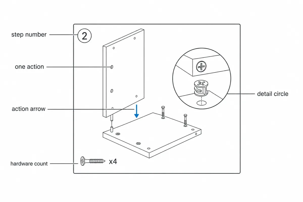
The step panel is the atomic unit of step by step assembly instructions, and the strong ones share a strict visual grammar. If you want the deep version, the post on arrows, parts, and fastener layout in assembly drawings covers each convention in detail; here is the short anatomy:

  • A big step number. The reader is tracking position in a sequence with their peripheral vision. Make the number impossible to miss.
  • One action. The panel shows a single verb happening. If you cannot caption the panel in five words, it is two panels.
  • Motion arrows. A bold arrow along the exact axis of movement — insertion, rotation, press. Curved arrows for turning, with the direction unambiguous. The arrow is the sentence.
  • Fastener callouts. The screw or cam drawn enlarged in a small circle, labeled with its letter and count ("B ×4"), connected by a thin leader line to where it goes. Hardware confusion is the number-one assembly failure, so the hardware gets its own visual channel.
  • Bold new, faded old. Parts being acted on this step in full line weight; everything already installed in light grey. The eye lands on the work instantly.
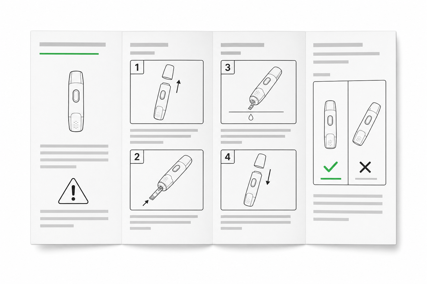
  • Orientation cues. Where a part can go in wrong, show the distinguishing feature — the finished edge, the keyed slot — and if needed a small ✗/✓ pair showing the wrong and right way.
  • As little text as possible. Words are a fallback for what the drawing failed to show. Every label you delete is one less thing to translate and one less place to be misread.

Annotated anatomy of an assembly instruction panel: step number, one action, action arrow, hardware count, and detail circle

A panel with this grammar is scannable in about two seconds, which is roughly the attention a kneeling customer with a screwdriver in one hand will give it.

Wordless assembly instructions (the IKEA-style approach)

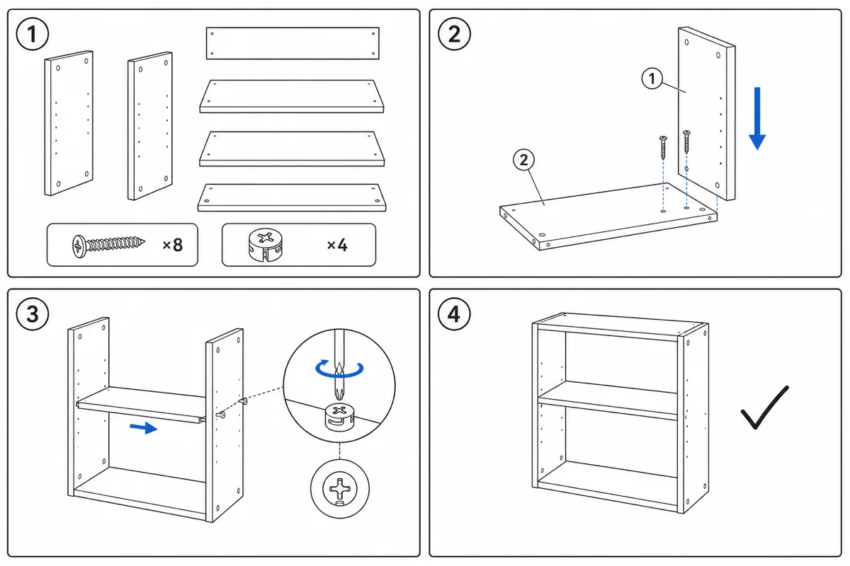
The furniture industry proved decades ago that assembly guides can work with almost no words at all — the style most people describe as "IKEA-style" instructions. (The term here describes a visual style only; ManualFig is not affiliated with or endorsed by IKEA.) Wordless assembly instructions are worth taking seriously for three reasons:

  1. They ship globally with one SKU. No translation, no multi-language booklet, no layout that breaks when German runs 40% longer than English.
  2. They force visual discipline. When you cannot fall back on a sentence, every ambiguity has to be resolved in the drawing — which makes the drawing better.
  3. They are faster to follow. Readers do not toggle between reading mode and doing mode; they just look and act.

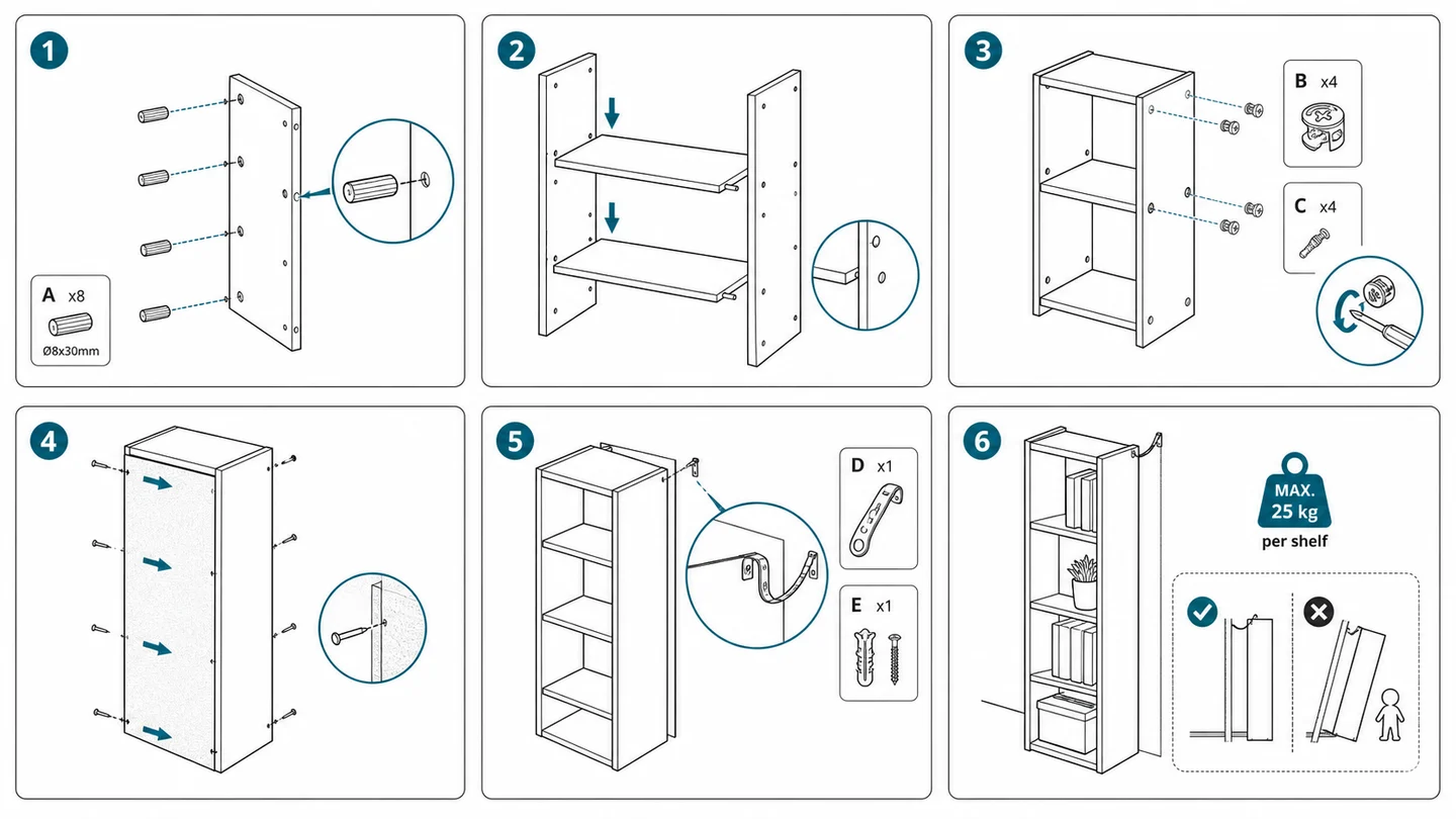
A wordless IKEA-style assembly sheet: four numbered panels from parts layout to finished bookshelf, no words

The conventions that make wordless layouts work: numbers for sequence, arrows for motion, enlarged circles for fasteners and detail views, ✗/✓ panels for the classic mistakes, a person silhouette wherever two people or a specific posture is required, and a phone icon pointing to support as the only "text" on the page. Scale cues matter more than usual — draw the fasteners at their real relative sizes so a reader can hold a screw against the page and confirm the match.

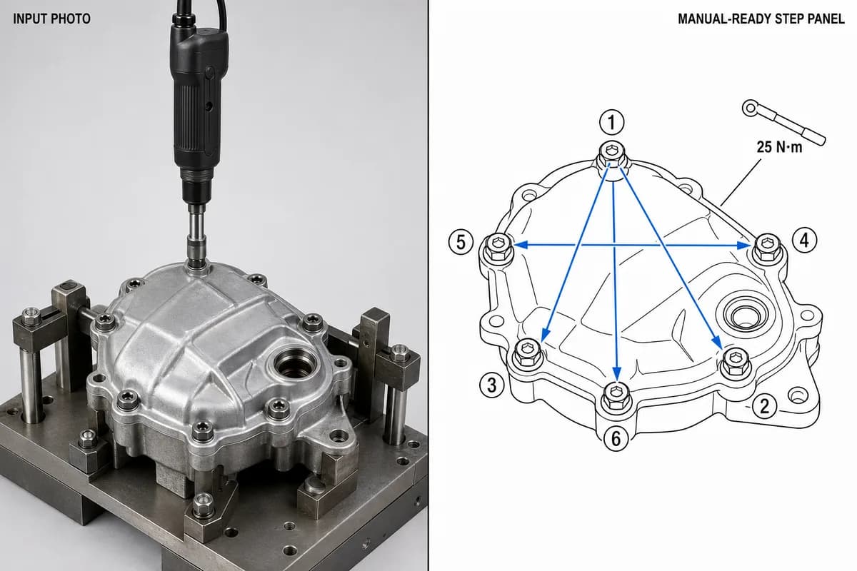
Going wordless is a spectrum, not a switch. Many strong manuals are mostly wordless: pure pictogram steps, plus one caption only where a step genuinely cannot carry itself — a torque value, a "do this before that" warning. If a caption survives your editing pass, keep it under seven words.

Assembly instructions examples

Abstract rules are easier to apply after seeing them in the concrete. Here are three assembly instructions examples across the categories that generate the most support volume.

Example 1: flat-pack furniture (a bookshelf)

Sequence: parts and hardware overview → exploded overview → cam-lock dowels into side panels (arrow on insertion axis, callout "A ×8") → shelves onto dowels (both hands shown on the silhouette; this is the two-person step, marked with the two-person pictogram) → cam locks rotated 90° (curved arrow, ✗/✓ detail circle showing under-rotated vs locked) → back panel nailed on (✗/✓ for finished-side orientation) → upright, with the wall-anchor step drawn as its own mandatory panel, not a footnote. Furniture rewards the wordless treatment more than any other category — the Furniture Assembly Instructions Generator is tuned for exactly this panel style.

Example 2: consumer electronics (a monitor stand and mount)

Electronics assembly is short but unforgiving: fine-thread screws, fragile connectors, one correct orientation. The example manual runs five panels: base bolted to riser (fastener callout with thread size), VESA plate to monitor back (detail circle enlarging the screw seats — the step where people over-torque into the panel, so a hand-tighten pictogram appears here), monitor lowered onto stand hook (arrow shows the angle of approach, not just direction), cable routed through the clip, and a final ✓ panel showing the correct standing state. Note the detail circles do the heavy lifting; at natural scale these features are millimeters wide.

Example 3: outdoor equipment (a gas grill)

Outdoor equipment means many similar fasteners, large awkward parts, and a safety-relevant end state. The manual opens with a hardware chart drawn at 1:1 scale so bolts can be matched against the page. The cart assembles in eight panels with bold-new/faded-old shading carrying the reader through visually similar frame steps. The gas-line connection panel breaks the wordless rule deliberately: it carries a caption and a leak-check step with a ✗/✓ soapy-water detail, because this is the step where an error is dangerous rather than annoying. Safety-critical steps earn words; everything else stays visual.

Across all three, the same grammar repeats — numbered panels, one action, arrows, callouts, ✗/✓ for known traps. Only the subject changes.

Common mistakes when creating assembly instructions

  • Writing the manual from memory instead of building the product with a notebook open
  • Photographing only the finished product, leaving no reference for intermediate steps
  • Merging steps to make the page count look smaller
  • Skipping the parts overview because "the parts are obvious" — they never are
  • Fastener callouts without counts, or hardware drawn at misleading scale
  • Arrows that show where a part ends up but not how it travels there
  • Leaving reversible parts unmarked and hoping for the best
  • Inconsistent art style across panels, which reads as three different documents stapled together
  • Shipping without a single cold-reader test
  • Treating the document as done forever — when the product revs, regenerate the affected panels instead of letting the manual drift out of date

FAQ

What software do I need to create assembly instructions?

You need something to draw the step figures and something to lay out the pages. The classic route is a CAD-based illustration suite (SOLIDWORKS Composer, Creo Illustrate, Cadasio), which requires the 3D model and the skills to drive it. The photo-based route generates the line-art panels directly from product photographs — the Assembly Instruction Illustration Generator covers the figure side — and any layout tool you already own handles the pages.

How do I create a work instruction versus an assembly instruction?

Same skeleton, different reader. An assembly instruction manual serves an end customer building a product once; how to create a work instruction is the factory-floor version of the same question — numbered visual steps for an operator who repeats the task all day, with torque values, quality checks, and revision control added. Start from a shared work instruction template and the two documents stay consistent.

How many steps should assembly instructions have?

As many as there are single actions — typically more than your first draft has. Splitting is almost always right: readers lose no time on a quick obvious step, but lose the whole build on a merged ambiguous one.

Should assembly instructions be wordless?

Default to wordless for consumer products shipped to multiple markets, and add captions only where a step is safety-critical or genuinely cannot be drawn. Most strong manuals end up 90% pictogram, 10% text.

Do I need CAD files to make assembly guides?

No. CAD is required by the traditional tool chain, not by the deliverable. Clear photographs of each assembly stage are a sufficient source for manual-ready line art, numbered panels, and exploded overviews.

Related: Exploded View Illustration Generator, Furniture Assembly Instructions Generator, Work Instruction Template.

全部文章

作者

avatar for Davie Chen / ManualFig AI
Davie Chen / ManualFig AI

研究者 · University of Arts in Poznan

Davie Chen 是 University of Arts in Poznan 动画与跨媒体学院的研究者,研究方向包括生成式 AI 在科学图像、专利插图、说明图和论文写作中的辅助应用。ManualFig AI 是这一研究方向延伸出的产品之一。

查看作者资料

分类

  • 指南
Why assembly instructions failHow to create assembly instructions in 7 stepsStep 1: Assemble the product yourself and log every actionStep 2: Photograph each stageStep 3: Group actions into steps — one action per stepStep 4: Open with a parts overviewStep 5: Generate a line-art panel for each stepStep 6: Assemble the layoutStep 7: Test on someone who has never seen the productAnatomy of a good assembly panelWordless assembly instructions (the IKEA-style approach)Assembly instructions examplesExample 1: flat-pack furniture (a bookshelf)Example 2: consumer electronics (a monitor stand and mount)Example 3: outdoor equipment (a gas grill)Common mistakes when creating assembly instructionsFAQWhat software do I need to create assembly instructions?How do I create a work instruction versus an assembly instruction?How many steps should assembly instructions have?Should assembly instructions be wordless?Do I need CAD files to make assembly guides?

更多文章

医疗器械 IFU 设计指南:版式、符号与插图实例
指南

医疗器械 IFU 设计指南:版式、符号与插图实例

面向医疗器械团队的 IFU 设计实务指南,涵盖页面结构、ISO 15223-1 符号、警告面板、线稿插图和可复用章节模板。
avatar for Davie Chen / ManualFig AI
Davie Chen / ManualFig AI
2026/08/01
图片转 SVG:如何得到 Illustrator 里真正可编辑的描边线稿
指南

图片转 SVG:如何得到 Illustrator 里真正可编辑的描边线稿

很多图片转 SVG 的结果在 Illustrator 里根本改不了线宽——因为线条被描成了填充轮廓。本文用两条工作流(直接生成 SVG、先生图再转换)拿到描边式、中心线风格的可编辑 SVG 线稿,附真实文件下载对比。

avatar for Davie Chen / ManualFig AI
Davie Chen / ManualFig AI
2026/07/28
How to Write Work Instructions (Step-by-Step, With Examples)
指南

How to Write Work Instructions (Step-by-Step, With Examples)

A practical guide to writing work instructions operators actually follow: the 9-step process, one-action steps, photos vs. illustrations, torque and QC callouts, and a reusable template.

avatar for Davie Chen / ManualFig AI
Davie Chen / ManualFig AI
2026/07/17
LogoManualFig.ai

AI 生成产品说明图示,分钟级获得接近合规交付的视觉资产。

工具
  • 照片转线稿
  • 装配说明
  • 作业指导
  • 爆炸视图
  • 故障排查
  • 全部工具
应用场景
  • 医疗器械 IFU
  • 制造业
  • 亚马逊与电商
  • 家具装配
  • 快速入门
资源
  • 博客
  • 术语表
  • 更新日志
  • 路线图
公司
  • 关于我们
  • 联系我们
  • Cookie政策
  • 隐私政策
  • 服务条款
© 2026 ManualFig.ai. All Rights Reserved.