AI Exploded View Generator
Generate exploded views from product photos or CAD screenshots
Separate parts along a clear axis, match numbered callouts to the BOM, and show fasteners and reassembly order.
Exploded view drawing
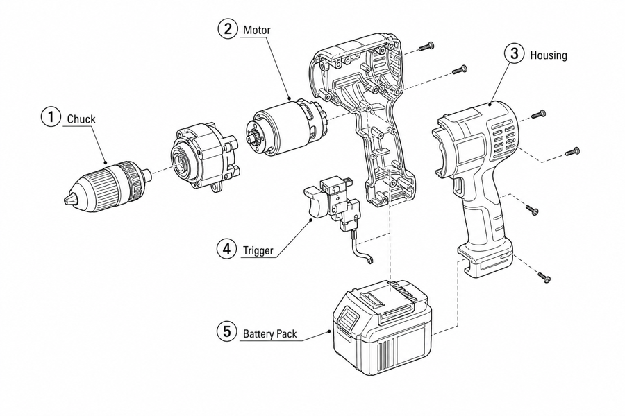 Example output
Output: manual-ready line art
What exploded views should include
Use exploded views when users need to understand how parts separate, align, and reconnect.
Part separation
Show each visible part away from the main body without losing the product relationship.
Callouts and fasteners
Add numbered labels, screws, clips, tabs, seals, washers, or detail circles.
Assembly context
Pair the exploded view with arrows, step panels, warnings, or final check states.
Exploded views for explanation, not manufacturing
Manual exploded views clarify how parts relate. Engineering dimensions and tolerances still belong in CAD.
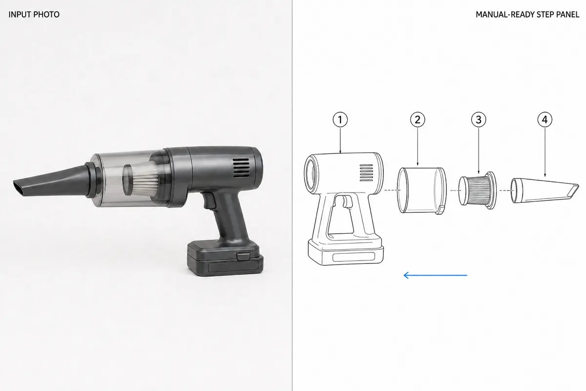
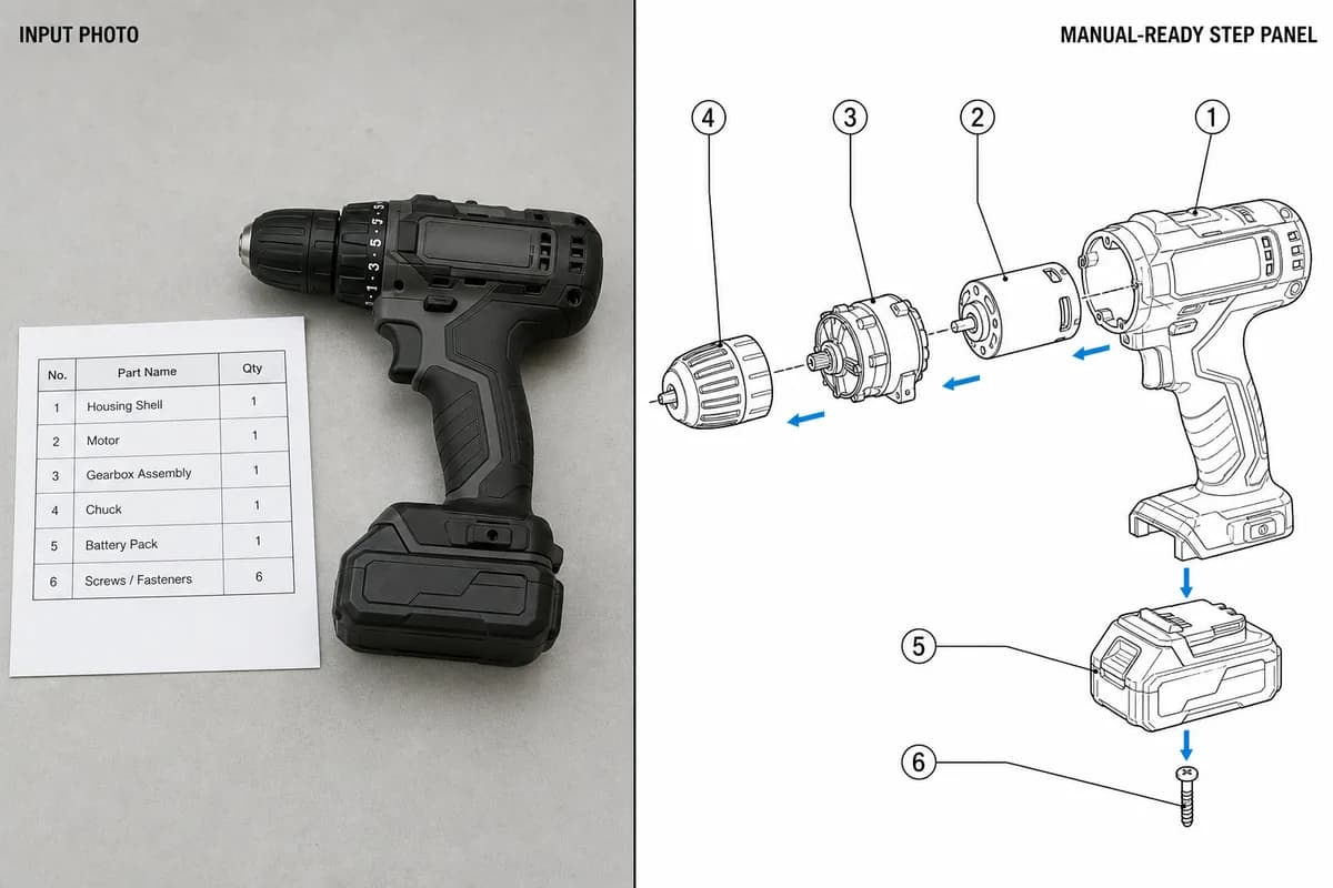
- Prompt: "Explode along the drive axis; number balloons ①–⑥ in the same order as this parts list."
- Human edits: reordered two balloons so numbering follows the reassembly order.
- Exported as SVG for the replacement-parts page.
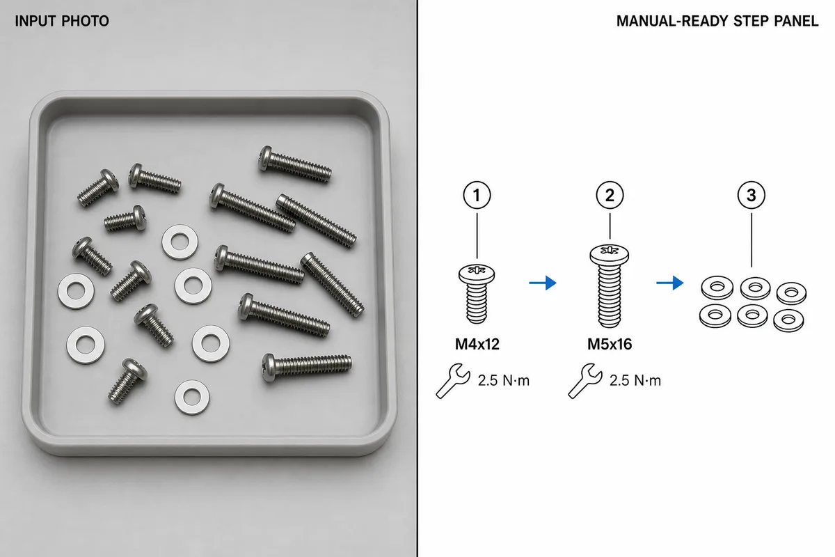
- Prompt: "Separate the fasteners into a labeled row: M4×12, M5×16, washers; add leader lines."
- Human edits: verified thread sizes against the drawing before publishing.
- Exported as PNG for the service bulletin.
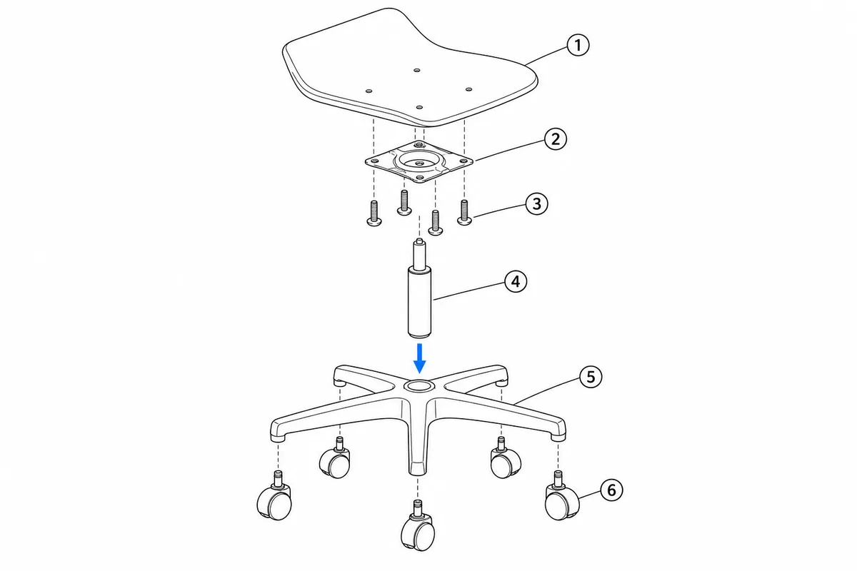
- Prompt: "Exploded view of an office chair base: seat pan, mounting plate, 4 screws, gas lift, five-star base, casters; number the balloons top to bottom."
- Human edits: none needed for the draft; a service manual would add the part numbers from the BOM beside each balloon.
- Typical use: a replacement-parts page or the overview figure at the start of an assembly guide.
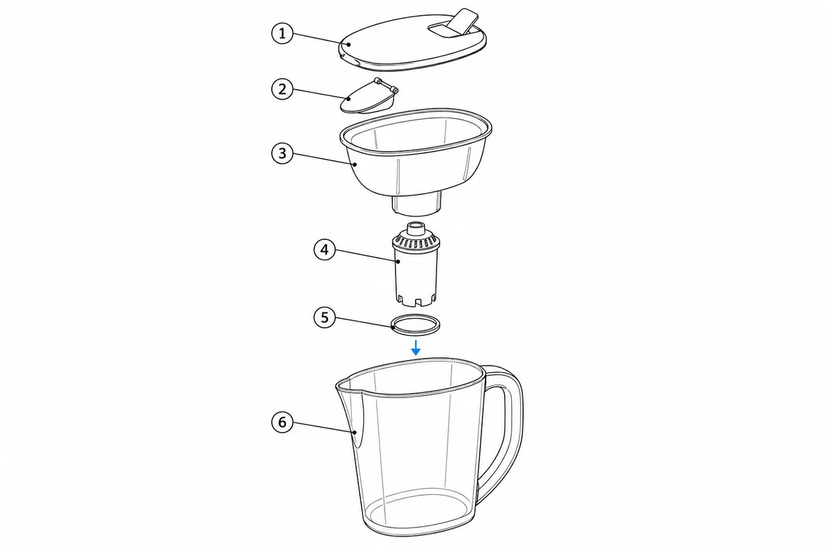
- Prompt: "Lid, pour flap, reservoir, filter cartridge, O-ring, jug; keep the O-ring as its own balloon."
- Human edits: none; the O-ring was the detail we checked first because it is the part users lose.
- Typical use: replacement-cartridge instructions and the parts page of a quick start guide.
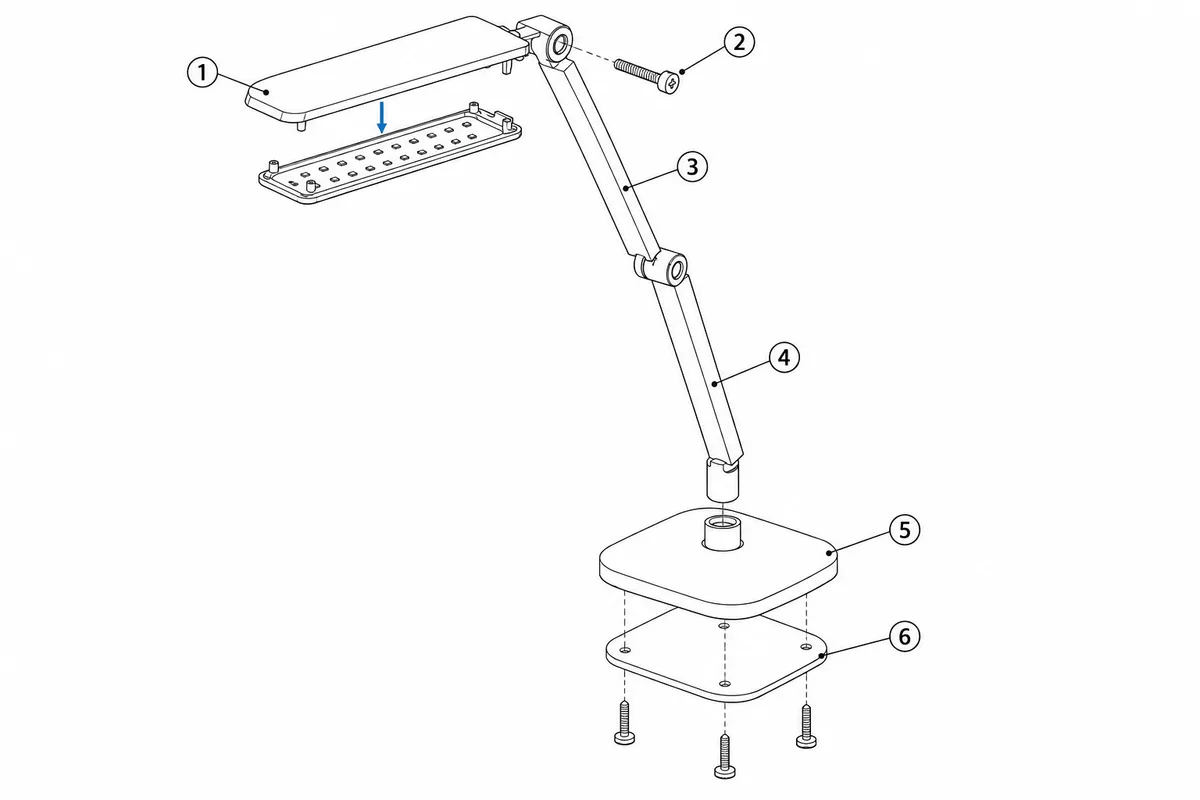
- Prompt: "Shade with LED module, hinge screw, upper arm, lower arm, base, weighted plate with 3 screws; explode along the assembly axes."
- Human edits: none for the draft; balloon ② (hinge screw) would be re-numbered to follow the BOM order.
- Typical use: a warranty page showing which parts are user-replaceable.
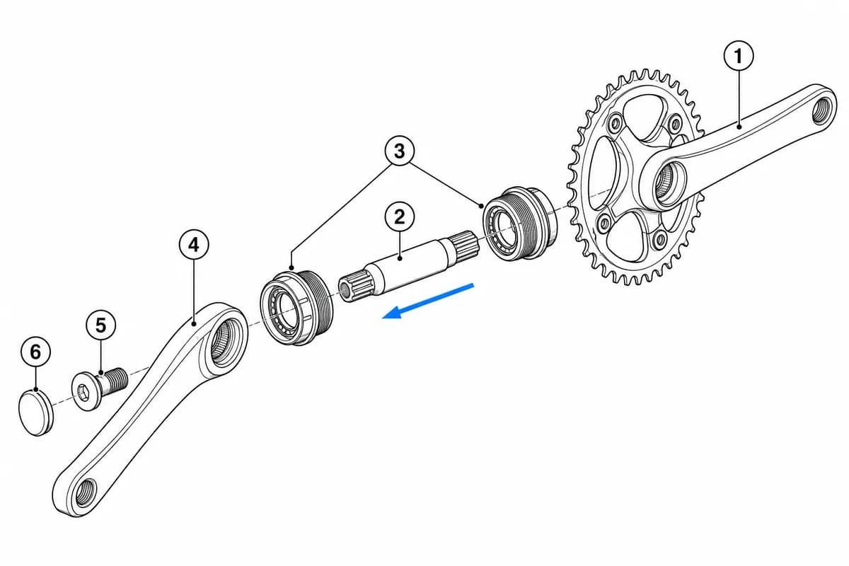
- Prompt: "Right crank with chainring, spindle, two bearing cups, left crank, crank bolt, dust cap; explode along the spindle axis."
- Human edits: none; a shop manual would add the bearing-cup thread direction as a note beside the figure.
- Typical use: bike service documentation and replacement-parts listings.
From product reference to manual-ready output
ManualFig keeps the prompt, uploaded references, generated options, revisions, and exports in one browser workflow.
Upload or describe the product
Start from a product photo, CAD screenshot, sketch, existing manual page, or a short step list.
Generate the instruction visual
Create line art, numbered panels, arrows, callouts, detail views, warnings, and completion checks.
Refine and export
Select a result, revise it with text, keep versions together, and export PNG or SVG for documentation.
When ManualFig fits — and when to go back to CAD
Exploded views for manuals explain how parts relate; engineering drawings carry the numbers. Use this boundary to decide where each figure belongs.
Good fit: explanation
Parts identification pages, replacement guides, reassembly order, numbered balloons, leader lines, and chapter-opener overviews.
Good fit: revision speed
Drafting a service-page exploded view from a photo or CAD screenshot in minutes, then editing balloons and arrows per review feedback.
Back to CAD
Dimensions, tolerances, section views for machining, certified BOM numbering, and any drawing a supplier will manufacture from.
Related ManualFig pages
ManualFig drafts explanatory exploded views for manuals, parts pages, and service guides. It does not replace dimensional CAD, tolerances, or manufacturing drawings; verify hidden geometry and part order before publication.
Exploded View Illustration FAQ
What is an exploded view drawing?
An exploded view drawing shows the parts of a product separated along their assembly axes, so the viewer can see how every component fits together. Each part usually gets a numbered balloon and a leader line, and thin alignment lines show where it reconnects. Manuals use exploded views for parts identification, replacement guides, and assembly overviews.
Should I use an exploded view or a step-by-step sequence?
Exploded views answer "how do all the parts relate to each other" before the user starts. Step sequences answer "what do I do first, second, third." A first-time assembly guide usually needs steps; a replacement-parts page or service overview usually needs an exploded view. Many manuals need both — one exploded view as the chapter opener, then step panels for each assembly stage.
Is this a CAD exploded view?
No. ManualFig creates explanatory documentation artwork. It does not replace CAD, manufacturing drawings, dimensions, or engineering validation.
Can I export exploded views as SVG?
Yes. Generated images can be converted to SVG for scalable documentation assets.
What references help most?
Product photos, CAD screenshots, part photos, sketches, existing manual pages, and part lists all help guide the output.
Create an exploded view for your manual
Upload product or part references, describe what should separate, and generate a manual-ready exploded view.