Visual Manufacturing Assembly Instructions
Create visual manufacturing assembly instructions
Turn process notes and station photos into numbered assembly, inspection, changeover, and quality-check panels.
Manufacturing work instruction
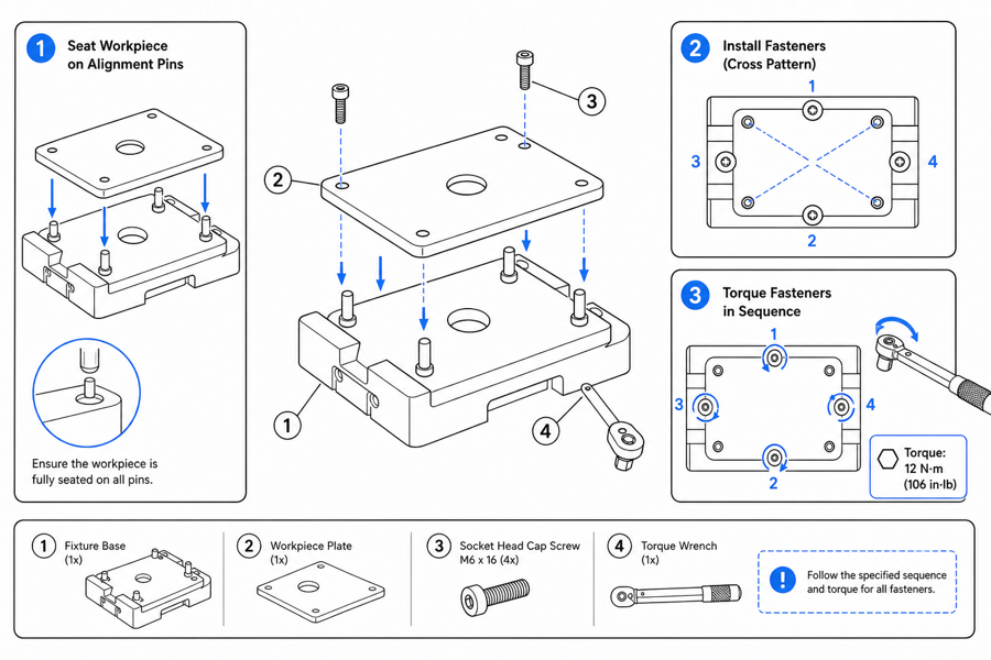 Example output
Output: manual-ready line art
Manufacturing assembly instructions for each station
Use illustrated steps where text alone causes rework, scrap, or slow training.
Assembly stations
Show part orientation, fastener order, and torque for each station.
Inspection and QA
Highlight what to check with numbered callouts and pass/fail states.
Changeover and setup
Document setup and changeover steps so any operator can repeat them.
Real cases: input, output, and the human touch
Each case shows the reference we started from, the generated figure, and the edits a person made before export.

- Prompt: "Number the bolts in a star tightening order and add the torque value next to the wrench."
- Human edits: the certified torque value was entered by the process engineer, not generated.
- Exported as PNG for the MES station screen.

- Prompt: "One correct state with a check mark, two incorrect seatings with crosses; keep the part identical across panels."
- Human edits: QA renamed the failure labels to match the NCR codes used on the line.
- Exported as SVG for the printed traveler and PNG for training.
From product reference to manual-ready output
ManualFig keeps the prompt, uploaded references, generated options, revisions, and exports in one browser workflow.
Upload or describe the product
Start from a product photo, CAD screenshot, sketch, existing manual page, or a short step list.
Generate the instruction visual
Create line art, numbered panels, arrows, callouts, detail views, warnings, and completion checks.
Refine and export
Select a result, revise it with text, keep versions together, and export PNG or SVG for documentation.
Manufacturing work instruction example: torque-controlled assembly
A station instruction has to answer four things in one glance: which fastener, in what order, at what torque, and how to verify. The case above shows how a station photo becomes a numbered tightening sequence with the torque value carried as a callout — with the certified value supplied by the process engineer.
Fastener sequence
Star or cross tightening order as numbered balloons directly on the line art.
Torque callouts
Values sit next to the tool icon; the generator draws the callout, engineering owns the number.
Verification cue
A final panel shows the torque-marked bolts or the click-wrench confirmation.
Quality checkpoints and correct-vs-wrong states
Inspection figures work when the operator can compare the part in hand against a pass state and the named failure states. Keep the part drawing identical across panels so only the defect differs.
Pass state
The correct seating, alignment, or surface with a check mark and a short label.
Named failure states
Each reject panel carries the same label your NCR or defect codes use on the floor.
Decision cue
What the operator does next: accept, rework at the station, or route to QA.
What ManualFig exports to shop-floor systems
Output is standard PNG and SVG, so figures drop into whatever already runs the line — no integration project required.
MES and station screens
High-resolution PNG panels sized for full-screen station displays.
Printed travelers and SOPs
SVG keeps line work crisp at any print size for travelers and work cards.
Training material
The same figures reused in onboarding decks and LMS lessons, so the floor and the classroom match.
What a manufacturing work instruction contains
Whether it lives on a station screen or a printed traveler, a manufacturing assembly instruction is a fixed set of fields. ManualFig draws the figure for each step; the values inside it come from the released process documentation.
Step number and one action
One numbered step per figure with a single verb: place, align, torque, inspect. Multi-action steps are the first thing operators skip.
Parts, tools, and consumables
The part number, the tool, and any adhesive, grease, or PPE the step needs, shown in the panel and listed beside it.
Torque, sequence, and settings
Fastener order as numbered balloons, the torque value as a callout, and machine settings written exactly as the traveler states them.
Related ManualFig pages
ManualFig helps manufacturing teams draft the visual part of work instructions. Engineers and quality owners still approve torque values, tools, PPE, acceptance criteria, revision state, and every safety-critical instruction.
Manufacturing work instructions FAQ
Is this a work instruction software like Dozuki, VKS, or Scribe?
No. Those platforms manage, distribute, and track work instructions on the floor. ManualFig produces the illustrated step figures that go inside them: export PNG or SVG and drop the figure into your existing work instruction software, MES, or printed traveler. If you are still choosing a platform, start with the digital work instructions overview and the free work instruction template linked below.
Does this replace engineering drawings?
No. ManualFig produces explanatory work-instruction figures, not CAD, GD&T, or engineering-validated drawings.
Can I show torque and fastener order?
Yes. Describe the values and sequence and the figure adds callouts and a numbered order with arrows.
Can operators read it on a screen and on paper?
Yes. Export high-resolution PNG for screens and SVG or PNG for printed travelers.
Generate a manufacturing work instruction
Describe the station step or upload a reference, generate the figure, then refine and export.