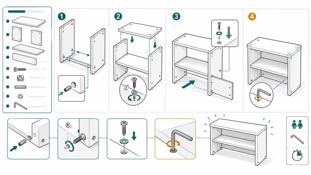
Assembly Instruction Drawings: Arrows, Parts, Fasteners, and Layout
A practical guide to assembly instruction drawings: panel structure, arrows, part callouts, fastener details, warnings, and final checks.
Assembly instructions fail when the reader cannot tell which part goes where, which side faces up, or which fastener belongs in the step. Good assembly drawings remove that ambiguity.
ManualFig can generate assembly visuals from part photos, CAD screenshots, sketches, and step lists. The best results come from describing the part, the action, the orientation, and the final state.
Start from the Assembly Instruction Illustration Generator.
Common mistakes to avoid
Assembly drawings become confusing when they try to do too much at once. A single panel that shows three parts, two fasteners, one tool, and a final product state may look efficient on the page, but the reader has to decode it while holding the product.
The common mistakes are predictable:
- Showing parts from a different angle than the user sees on the table
- Omitting the "this side up" or "front faces forward" cue
- Using one arrow for two actions, such as insert and rotate
- Drawing screws, washers, dowels, and clips at the same scale as the product
- Placing the fastener list far away from the step that needs it
- Showing only the action, not the completed lock, click, flush fit, or alignment state
- Reusing a beautiful exploded view when the reader needs a sequence
Good assembly art is not just a parts diagram. It is a guided path from loose parts to the next stable state.
Use one action per panel
Each panel should answer one assembly question:
- Which part is used?
- Where does it go?
- What direction does it move?
- Which fastener or tool is required?
- What should the finished state look like?
If one panel answers too many questions, split it.
For example, "insert the dowel and attach the side panel" should usually become two panels. The first panel shows dowel orientation and hole placement. The second panel shows the side panel moving into position. The reader should not have to guess which action happens first.
Arrows carry the action
Use straight arrows for insertion, curved arrows for rotation, and ghost outlines for before/after states. For screws and locks, show the final state too. Users need to know not only what to do, but when the step is done.
Use arrow types consistently:
- Straight arrow: insert, slide, push, pull, align
- Curved arrow: rotate, tighten, turn, twist, fold
- Dotted arrow: optional route, cable path, view direction, hidden movement
- Double arrow: adjust, center, level, or test range
- Ghost outline: before/after position
- Zoom circle: small hardware detail that is too small in the main panel
When a motion has a direction and an end condition, show both. For a cam lock, the curved arrow is not enough. Add the final slot orientation or a check mark state.
Parts and fasteners need their own hierarchy
Fasteners cause many assembly mistakes because they look similar at a glance. If your product uses several screw lengths or clips, do not rely on a text list alone.
Use detail callouts for:
- Screw length and head type
- Dowel orientation
- Washer order
- Clip direction
- Bracket left/right orientation
- Cam lock rotation
- Adhesive pad placement
- Cable tie routing
If the product has a bill of materials, match the callout names to the BOM. If the public manual uses neutral labels like A, B, C, keep those labels consistent across the whole document. On a production line the same discipline applies with higher stakes — manufacturing work instructions add torque values and fastener sequences on top of the callout hierarchy described here.
Prompt templates
Start with the assembly sequence:
Create a four-panel assembly instruction drawing for a flat-pack shelf.
Panel 1: identify the side panels and top shelf.
Panel 2: insert dowels into the side panel holes.
Panel 3: align the top shelf and push downward.
Panel 4: tighten the cam locks and show the completed shelf.
Use clean black line art, numbered panels, arrows, part callouts, and a small anti-tip warning.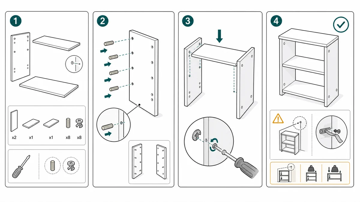
Add a detail prompt when fasteners are easy to mix up:
Create a close-up fastener callout for an assembly manual.
Show screw A as a short flat-head screw and screw B as a longer round-head screw.
Place them beside the matching holes and add leader lines to the correct location.
Use clean line art, high contrast, no brand text, no decorative background.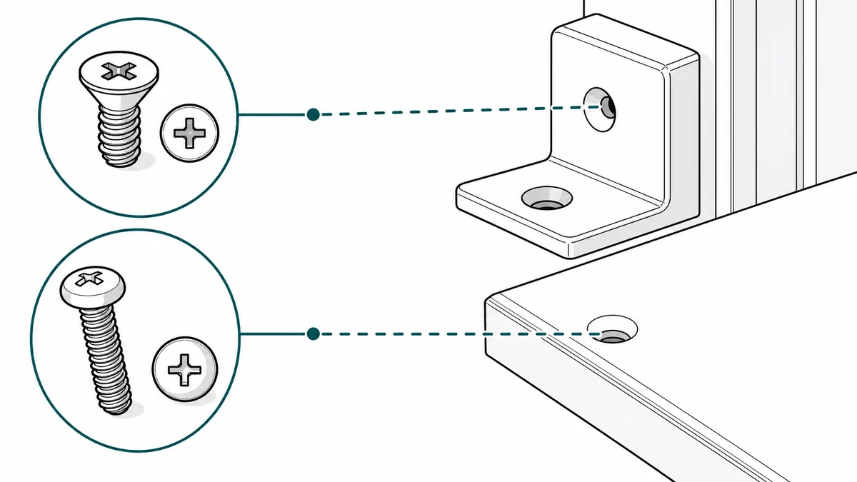
Use a correct/incorrect prompt when a part can be installed backward:
Create a correct/incorrect assembly panel for attaching a bracket.
Correct: the arrow mark on the bracket faces upward and the long slot points left.
Incorrect: the bracket is upside down with a red X.
Show both states side by side with clear orientation callouts.
Use manufacturer manual style line art, white background, minimal labels.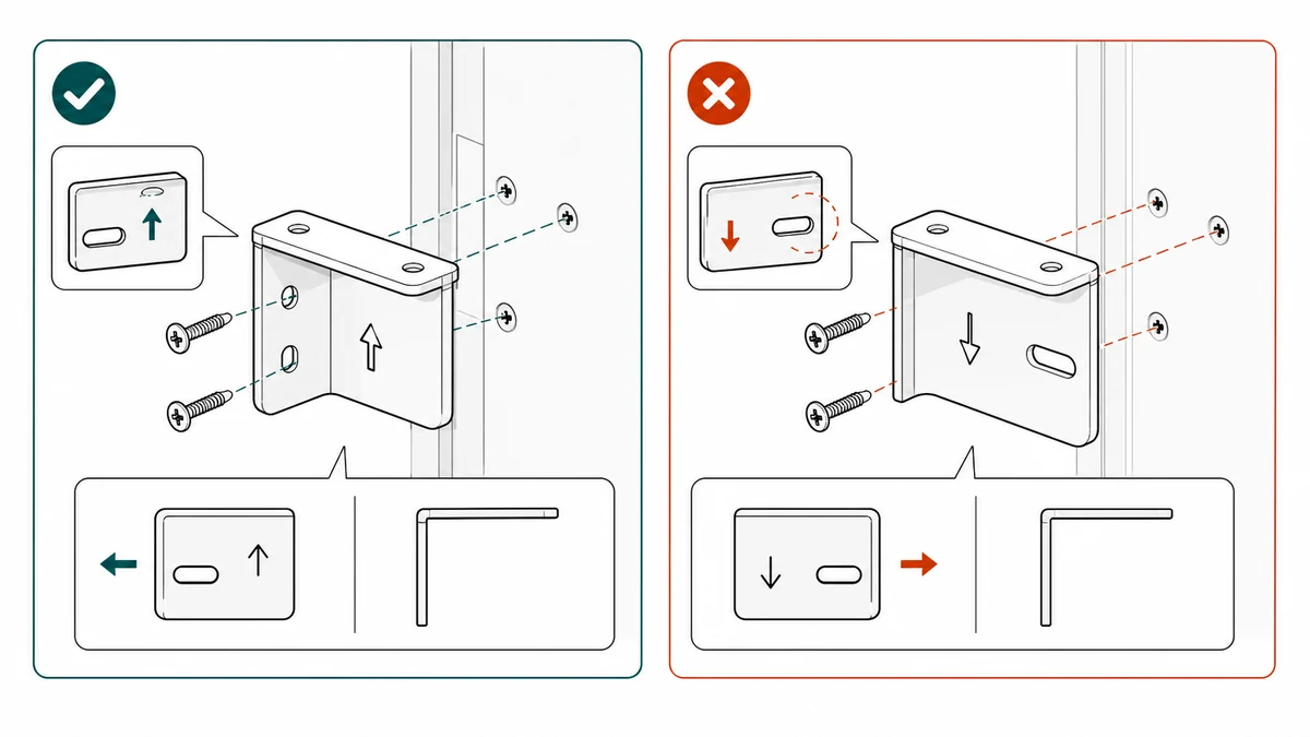
A practical ManualFig workflow
ManualFig works best when the input separates product truth from layout preference.
- Collect the reference: part photo, CAD screenshot, supplier drawing, or a rough sketch.
- Write the parts list for the step, including labels, left/right names, and fastener IDs.
- Write one action per panel.
- Add orientation cues: front, back, top, underside, left side, notch facing out, cable channel facing down.
- Generate the panel set in ManualFig.
- Revise the panels where arrow direction, fastener detail, or final state is wrong.
- Export approved panels for the manual, packaging insert, or support article.
Do not wait until the entire manual is written to create the drawings. Assembly drawings often expose missing procedural details: an unmentioned washer, a hidden tab, a step that needs two hands, or a final state that cannot be described clearly in text alone.
When to use an exploded view
Use an exploded view when users need to understand the relationship between several parts before they start. Use step panels when users need to follow the order. Many manuals need both.
An exploded view helps when:
- Parts are similar and need naming
- The assembly is modular
- The user needs to identify replacement parts
- Support teams refer to parts by location
- A product manual needs an overview before the procedure
Step panels help when:
- The order matters
- The part can be installed in the wrong orientation
- Force, rotation, or alignment is involved
- A safety warning belongs to one step
- The final state needs confirmation
If you only have room for one, choose the format that answers the reader's immediate question. A replacement part page may need an exploded view. A first-time assembly guide usually needs steps.
Review checklist
Before publishing an assembly drawing, check:
- Can a first-time user identify every part in the panel?
- Does the camera angle match the user's working position?
- Are left/right and front/back orientation cues visible?
- Are fastener labels consistent with the parts list?
- Is each arrow attached to a single action?
- Does the drawing show the completed state of the step?
- Are warnings placed next to the risky action?
- Is any generated hardware detail inconsistent with the actual BOM?
ManualFig can draft the visual quickly, but the final assembly logic should still be reviewed by the product, engineering, or documentation owner.
Related pages: Exploded View Illustration Generator, Furniture Assembly Instructions Generator, and Product Manual Generator.
Author

Researcher · University of Arts in Poznan
Davie Chen is a researcher at the Faculty of Animation and Intermedia, University of Arts in Poznan, studying generative AI for scientific figure creation, patent illustration, instruction graphics, and manuscript drafting. ManualFig AI is one of the research-to-product tools built from this work.
View author profileCategories
More Posts
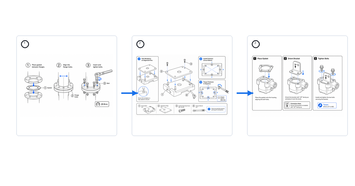
Work Instruction Examples and Samples (With Visuals)
Real examples of visual work instructions for assembly, inspection, and changeover — what a good sample looks like and how to generate your own.
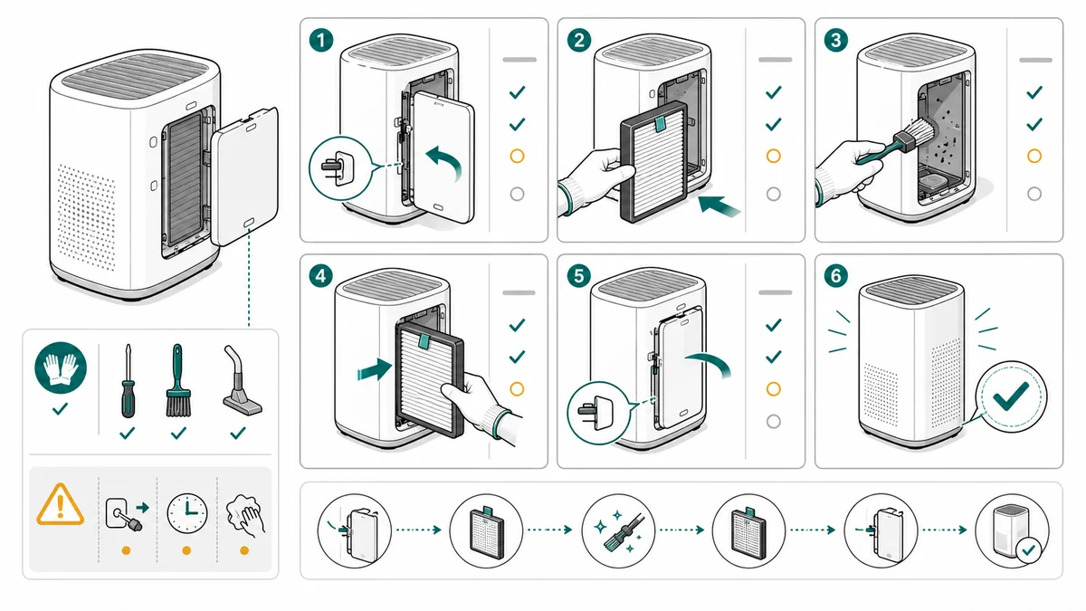
Maintenance Procedure Illustration Checklist
A checklist for creating maintenance procedure illustrations for cleaning, replacement, inspection, filters, service steps, warnings, and final checks.
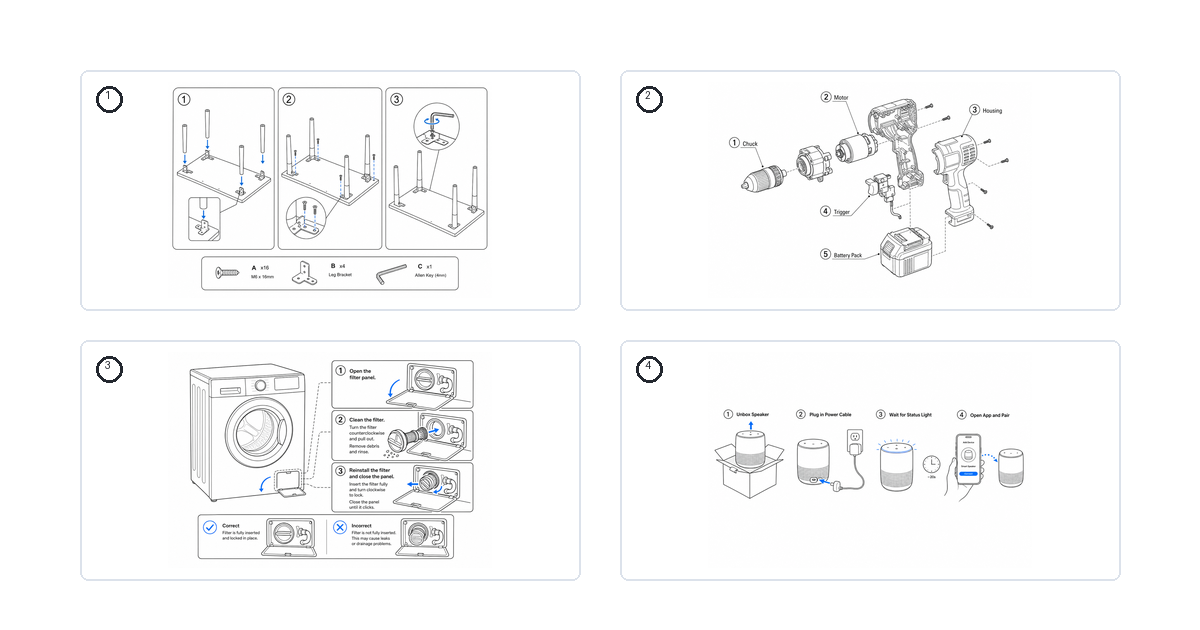
Assembly and Troubleshooting Guide Examples by Product Type
How to illustrate assembly and troubleshooting guides for common products — beds, cribs, grills, washing machines, water softeners, and more.