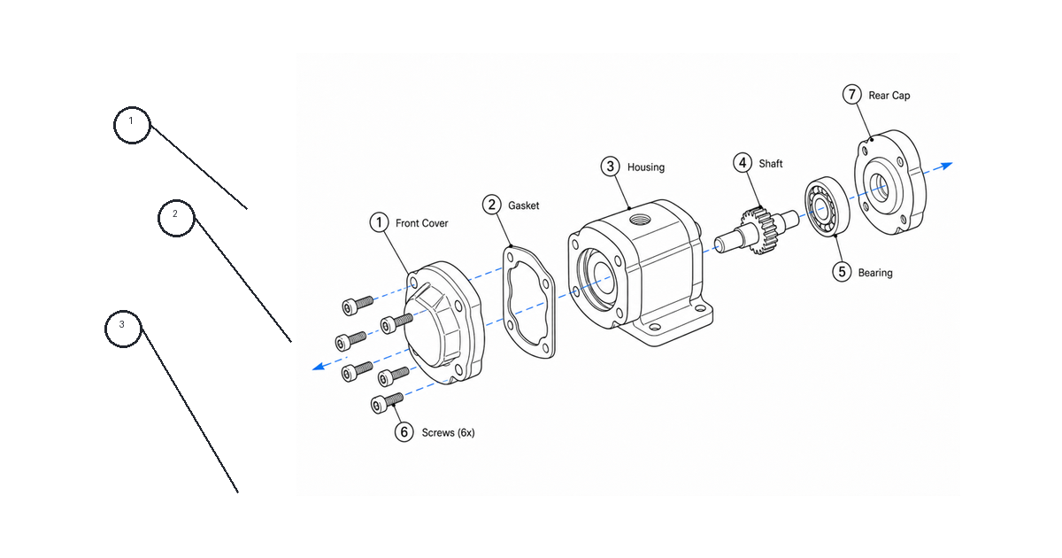
What Is an Exploded View Drawing? Definition and Examples
A plain-English definition of an exploded view drawing, when to use one, how it differs from a CAD/SolidWorks export, and how to generate one for a manual.
A customer emails support because the small plastic clip that holds their blender jar to the base has snapped. They want to order a replacement. The first question back from support is simple: which part? The customer does not know. There are four similar clips, two gaskets, and a coupling ring, and the product photo on the listing shows none of them clearly. Two days of back-and-forth follow — photos, guesses, the wrong part shipped — and a five-dollar component turns into a refund request.
An exploded view drawing is the document that prevents this. It shows the assembled product with its parts pulled apart along their assembly axes, connected by thin leader lines, so anyone can see how everything fits together. Each part gets a numbered balloon that maps to a parts list. The customer points at balloon 7, support reads "jar coupling clip," and the right part ships the same day.
Generate one with the Exploded View Drawing Generator.
What an exploded view drawing actually is
In plain English, an exploded view is a single image of one product where the components are spread out in space — as if the product gently flew apart and froze mid-air — but stayed lined up along the directions they were assembled. Nothing is rearranged randomly; a screw floats directly above the hole it goes into, a lid hovers above the body it caps.
That spatial logic is the whole point. A flat list of part names tells you what exists. An exploded view tells you where each part lives and how it connects to its neighbors. It answers, before anyone touches a tool, the two questions that drive most support tickets and assembly mistakes: what are the parts, and how do they relate?
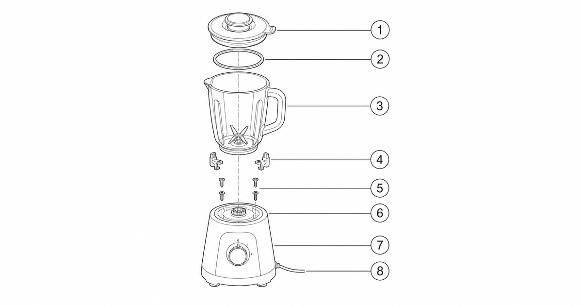
The version that belongs in a manual is deliberately simple: clean black line art on a white background, numbered balloons, and just enough detail to identify each part. It is not a rendering, not a photo, and not an engineering drawing with dimensions. Its only job is to be read quickly by a customer, technician, or assembler.
When to use an exploded view
An exploded view earns its place whenever a reader has to understand a product as a set of separable parts rather than a single object. The most common situations:
- Parts lists and BOM diagrams — number every component so each balloon maps to a row in an order form or bill of materials. This is what turns "the broken clip" into "part 7, SKU BL-204."
- Service and repair guides — show disassembly order and how parts seat together, so a technician removes things in the right sequence and nothing gets forced.
- Assembly manuals — open a section with an exploded overview before the step-by-step panels, so the reader sees the whole structure before following individual steps.
- Replacement and spare-parts ordering — give customers a reliable way to identify exactly what they need without describing it in words.
- Training and warranty documentation — a shared reference everyone points to with the same numbers.
If your reader only needs to press one button or open one cover, a simple callout drawing is enough. Reach for an exploded view the moment the product comes apart, or the moment someone needs to order a piece of it.
Exploded view drawing vs a CAD/SolidWorks export
This is where a lot of confusion lives, so it is worth being precise. A SolidWorks (or any CAD) exploded view is generated from a 3D model for engineering purposes. It is tied to real geometry, tolerances, and the manufacturing data behind the part. It is accurate, heavy, and built to drive production.
A manual exploded view is a different deliverable with a different audience. It is an explanatory documentation drawing: simplified line art, numbered balloons, a white background, and only the parts the reader cares about. It is made to be read by a customer or a service tech — not to drive a CNC machine.
The practical differences:
- Source — a CAD export needs a complete 3D model; a documentation drawing can be made from a product photo, a single CAD screenshot, or a supplier image.
- Detail — CAD shows every fillet and thread; a manual drawing shows what helps identification and hides the rest.
- Purpose — CAD feeds manufacturing and validation; documentation feeds understanding.
- Effort — building an exploded view in SolidWorks means owning the model and the software; a documentation version can be generated from a reference in minutes.
ManualFig produces the documentation version. It does not replace CAD, dimensions, or engineering validation — if those matter, route the figure through the responsible engineer. But for the manual, the insert, and the parts page, the documentation drawing is usually the better fit because it is cleaner, lighter, and far faster to make.
What a good exploded view includes
A strong exploded view is not just "parts spread apart." Several elements separate a useful drawing from a confusing one:
- Parts separated along clear assembly axes, not floating randomly. Each component sits on the line it travels during assembly, so the reader's eye can reassemble the product mentally.
- A numbered balloon and leader line for every component. Balloons are the small circled numbers; leader lines are the thin lines connecting each balloon to its part. Together they tie the drawing to the parts list.
- Fasteners and hardware called out separately. Screws, washers, nuts, and clips are easy to lose visually. Give them their own balloons or group them in a hardware callout so nobody guesses.
- Consistent line weight and spacing. Parts should be far enough apart to read but close enough that the relationships stay obvious.
- An optional enlarged section detail for a critical or tricky fit — a small magnified circle showing exactly how two pieces seat together.
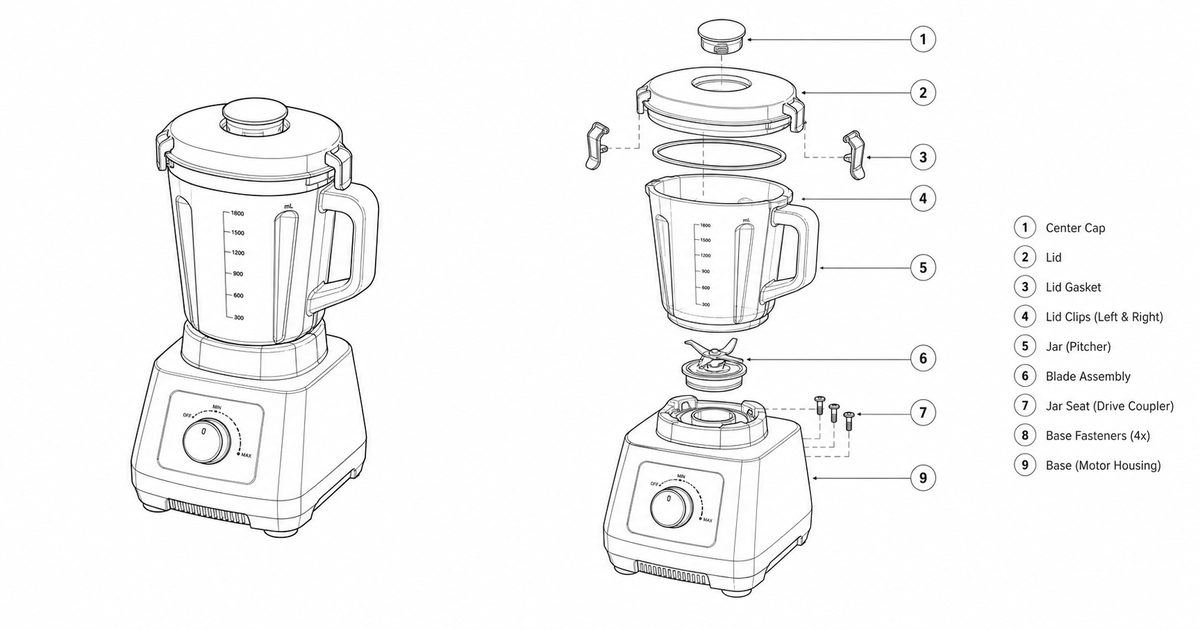
Place the assembled product and its exploded view side by side and the document becomes self-explaining: the reader sees the finished object and the same object opened up, with every part numbered and traceable.
How to make one from a product or CAD reference
You do not need to model the product in CAD to get a clean documentation drawing. The fastest path is to start from a reference you already have and describe what you want:
- Gather the best reference — a clear product photo, a CAD screenshot, a supplier image, or an existing manual page. The clearer the part separation in the source, the better the result.
- Decide the purpose — parts list, service guide, or assembly overview. This determines how many parts you call out and how much detail each needs.
- Name the parts that must be numbered, especially anything a customer might order separately.
- Choose the view — usually an isometric (three-quarter) angle, because it shows depth and lets parts separate cleanly along their axes.
- Generate the drawing, then review whether every part has a balloon and whether the separation reads logically.
- Refine — renumber, group the hardware, add a detail circle, or simplify a crowded area.
A prompt that produces a clean manual-ready exploded view looks like this:
Create an exploded view line drawing from this product reference.
Pull each part apart along its assembly axis on an isometric view.
Add a numbered balloon and thin leader line to every component.
Call out fasteners and hardware separately with their own balloons.
Use black line work on a white background, thin leader lines, no shadows, no logo, no dimensions.
Leave room for a parts list beside the drawing.
For a service guide where disassembly order matters, make the sequence explicit:
Create an exploded service diagram for this product.
Separate parts in disassembly order, top to bottom.
Number each part in the order it is removed.
Add one enlarged detail circle on the gasket-to-housing fit.
Keep clean manual line art, white background, no engineering dimensions.
Once generated, you can keep editing in the full workbench — renumber parts, highlight the hardware, add a detail circle — then export PNG or SVG.
Common mistakes to avoid
- Floating parts with no axis logic. If a screw drifts sideways from its hole, the reader loses the assembly relationship. Keep every part on the line it actually travels.
- Skipping the hardware. The clips, washers, and screws are exactly the parts customers break and reorder. Unnumbered hardware is the most common cause of wrong-part orders.
- Balloons that do not match the list. Renumber the drawing and the parts list together, every time. A mismatch is worse than no numbers at all.
- Cramming too many parts. If a section is dense, use a detail callout or split into two drawings rather than overlapping leader lines.
- Treating it like CAD. Adding dimensions, tolerances, or compliance marks to a documentation drawing implies an accuracy it does not carry. Keep those in the engineering file.
- Inventing details. Generated art should not add logos, model numbers, or parts that are not in the reference.
FAQ
What is the difference between an exploded view and an assembly drawing?
An exploded view shows all parts pulled apart so you can identify and locate each one. An assembly drawing typically shows the product assembled, often with steps for putting it together. Many manuals use both: an exploded overview to introduce the parts, then assembly steps to put them in order.
Do I need CAD or SolidWorks to make an exploded view?
No. CAD is one way to produce one, and it is the right tool when you own the 3D model and need engineering accuracy. For a manual, parts list, or service guide, a documentation drawing generated from a product photo or screenshot is faster and usually clearer for the reader.
What do the numbered circles and lines mean?
The numbered circles are called balloons, and the thin lines connecting them to parts are leader lines. Each balloon number corresponds to a row in the parts list, so a reader can point at a number and find the part name, quantity, and order code.
What view angle works best?
An isometric or three-quarter angle is standard. It shows the product's depth and lets parts separate cleanly along their assembly axes, which a flat front view cannot do as well.
Related: Exploded View Illustration Generator, Assembly Instruction Illustration Generator, Technical Illustration Generator.
Author

Researcher · University of Arts in Poznan
Davie Chen is a researcher at the Faculty of Animation and Intermedia, University of Arts in Poznan, studying generative AI for scientific figure creation, patent illustration, instruction graphics, and manuscript drafting. ManualFig AI is one of the research-to-product tools built from this work.
View author profileCategories
More Posts

Manufacturing Assembly Instructions: Format, Examples, and How to Illustrate Each Station
What a manufacturing assembly instruction must contain, how to lay out one step per page, three worked station examples (torque, orientation, inspection), and a template you can copy.
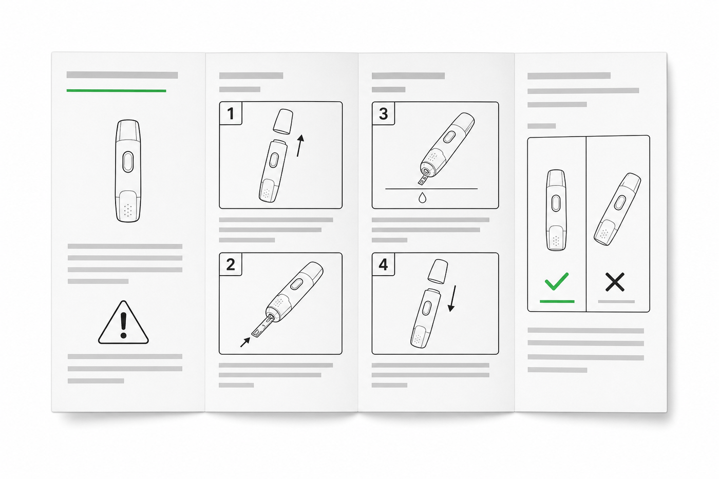
IFU Design Guide: Layout, Symbols & Examples
Practical IFU design guidance for medical devices: page layout, ISO 15223-1 symbols, warning panels, illustrations, and a reusable section template.
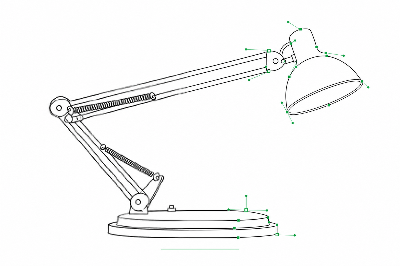
Image to SVG for Illustrator: How to Get Editable Strokes for Technical Line Art
Why many image-to-SVG conversions arrive in Illustrator as filled outlines you can't restyle — and two workflows that produce stroke-based, centerline-style SVG line art with adjustable line weights.