
Manufacturing Assembly Instructions: Format, Examples, and How to Illustrate Each Station
What a manufacturing assembly instruction must contain, how to lay out one step per page, three worked station examples (torque, orientation, inspection), and a template you can copy.
Station 14 builds the same gearbox cover four hundred times a shift. The assembly instruction taped to the fixture says "Install cover, torque bolts to spec." Every new operator asks the same three questions in the first hour: which bolt first, what is "spec," and how do I know it is right. The line lead answers them from memory, and the instruction stays exactly as useless as it was.
This guide is about fixing that document. It covers what manufacturing assembly instructions are (and how they differ from an SOP or a process sheet), the fields every station instruction needs, the one-step-per-page format that operators actually read, three worked examples, and a template you can copy into your own system. When you reach the figures, the Manufacturing Work Instructions Generator turns a station photo into a numbered, torque-annotated panel in a few minutes.
What "manufacturing assembly instructions" means
The terms overlap on most shop floors, so pin them down first:
- A process sheet or router lists the operations a part goes through, in order, with station numbers and standard times. It says where and in what sequence, not how.
- A standard operating procedure (SOP) describes how a role performs a whole task, often across several stations, including responsibilities and exceptions.
- A manufacturing assembly instruction is a work instruction for one station: how one operator performs one assembly task, right now, with the parts, tools, sequence, values, and pass criteria for that station alone.
If a document explains why a torque value was chosen or who approves changes, that content belongs in the process FMEA or the control plan. The assembly instruction is the last document before hands touch parts. Everything in it has to survive being read in eight seconds, standing up, with gloves on.
The fields every station instruction contains
Whether the instruction lives on an MES screen, a tablet, or a laminated traveler, the same seven fields appear. Treat missing fields as defects in the document.
| Field | What it holds | Who owns the value |
|---|---|---|
| Step number and action | One numbered step, one verb: place, align, torque, inspect | Manufacturing engineer |
| Parts and quantities | Part number, description, quantity per unit | BOM / engineering |
| Tools and consumables | Tool ID, socket size, adhesive or grease, PPE | Manufacturing engineer |
| Sequence and settings | Fastener order, torque value, press force, machine program | Process engineer |
| Figure | A photo or line drawing of this step, not the finished product | Documentation / ManualFig draft |
| Pass and fail criteria | The correct state plus named failure states with defect codes | Quality |
| Revision block | Document number, revision, effective date, approvals | Document control |
Two of these deserve a note. The figure is the field most often filled with a photo of the completed assembly, which shows the operator nothing about the step in front of them. And the revision block is the one field that must never be generated or copied from a similar instruction; it is filled in by the release process, or the instruction is not valid.
Format: one step per page, figure first
The format that survives contact with a real line is simple. Each page, screen, or card holds one step. The figure occupies the left two-thirds; the text sits to the right in the same order every time: action, parts, tool, values, check. The step number is large enough to read from the fixture.
A few rules that follow from that layout:
- One action per step. "Place gasket and install cover" is two steps. When an operator is interrupted between them, the gasket gets forgotten.
- Values in the figure, not only in the text. A torque value drawn next to the wrench is read; the same value in a sentence is skipped. The figure should carry the number, and the text should repeat it.
- Same viewpoint every step. If step 3 shows the part from the operator's side, step 4 does too. Rotating the view between steps is the most common cause of mirrored assemblies.
- Photos for identification, line drawings for action. A photo tells the operator which part to pick up. A line drawing shows which way it goes, because it can leave out the reflections, the cable in the background, and the fixture. Most stations need both: a small photo of the part and a larger drawing of the action.
- Correct-vs-wrong panels only where failures happen. A check-versus-cross pair for every step trains operators to ignore them. Reserve them for the steps that produced NCRs last quarter.
If you already run instruction software on the floor, the digital work instructions overview covers how illustrated steps drop into MES, tablets, and station screens without an integration project.
Three worked examples
Example 1: torque-controlled bolting station
Task: install a gearbox cover with six M8 bolts.
- Step 7 of 12. Action: Torque cover bolts in star sequence.
- Parts: cover assembly 4471-02 ×1, bolt M8×25 flange ×6 (already started by hand in step 6).
- Tool: click wrench T-114, 13 mm socket. Setting: 25 N·m.
- Sequence: star pattern ①–⑥ as numbered on the figure.
- Check: all six bolts show the torque mark; wrench clicked once per bolt.
- Failure states: bolt without mark (D-041), cover gap at any corner (D-017).
The figure is a line drawing of the cover from the operator's side, six balloons in star order, a wrench icon with "25 N·m" beside it, and one small panel showing the torque-marked bolt head. The value is entered by the process engineer; the drawing carries it. That is exactly the case shown at the top of this article: a station photo in, a numbered tightening sequence out, the certified number supplied by engineering.
Example 2: keyed connector orientation
Task: seat a wiring harness connector into a keyed socket.
- Step 4 of 9. Action: Insert harness connector until the latch clicks.
- Parts: harness 5510-11 ×1.
- Tool: none. PPE: standard.
- Orientation: key tab faces up; the figure shows the tab with a blue arrow toward the socket.
- Check: latch flush with the socket body; a light pull does not release it.
- Failure states: connector rotated 180° (D-088), latch not engaged (D-089).
Here the failure is entirely about orientation, so the figure is a correct-vs-wrong pair: the keyed tab up with a check mark, the tab down with a cross, the connector drawn identically in both panels so only the orientation differs. The pull check is a third small panel with an arrow.
Example 3: inspection checkpoint with pass and fail states
Task: verify the O-ring is seated before the housing is closed.
- Step 11 of 12. Action: Inspect O-ring seating in the groove.
- Parts: none added.
- Tool: none. Lighting: station lamp on.
- Check: O-ring fully in groove around the full circumference, no twist, no pinch at the two ribs.
- Failure states: O-ring twisted (D-102), O-ring pinched at rib (D-103), O-ring missing (D-104).
- Decision: pass, or rework at the station by reseating; a pinched ring is scrapped.
The figure is the seated O-ring with a check mark, then the two named failure states side by side, each with the defect code as its label. Quality owns those labels. When they change the code, the panel label changes with it, which is why the labels are text layers on an SVG, not baked into a photo.
How to illustrate each station
The figures are the slow part of writing manufacturing assembly instructions, which is why so many instructions ship with a photo of the finished unit. The workflow below produces one figure per step without a technical illustrator:
- Photograph the step, not the product. Stand where the operator stands. Take the photo at the moment the action happens: the bolt half-driven, the connector an inch from the socket.
- Write the step line first. Action, parts, tool, value, check. That line is the prompt.
- Generate the panel. In the Manufacturing Work Instructions Generator, upload the station photo, paste the step line, and ask for what the figure has to carry: "number the bolts in star order, add the torque next to the wrench," or "one correct state with a check, two failure states with crosses, keep the part identical across panels."
- Let the owners fill in the values. The generator draws the callout; the process engineer types the torque, and quality types the defect codes. Values that were generated rather than released have no place on a station.
- Export for the medium. PNG at full resolution for station screens, SVG for printed travelers and for any figure whose labels will change.
Steps 1 and 2 take longer than steps 3 to 5. That is the correct ratio; the generator is fast, the thinking about what the step must show is not.
A template you can copy
Paste this into your document control system, one block per step. The work instruction template page shows the same structure laid out for single-step, multi-step, torque, and correct-vs-wrong panels.
STATION: ____   STEP: __ of __   DOC: ________  REV: __  EFFECTIVE: ____-__-__
ACTION (one verb): ______________________________________________
PARTS:  P/N ________  qty __    P/N ________  qty __
TOOLS:  ________ (ID ____)   SETTING: ________   PPE: ________
SEQUENCE / VALUES: ______________________________________________
FIGURE: [one drawing of THIS step, operator's viewpoint, values drawn in]
PASS:   ________________________________________________________
FAIL:   ____________ (D-___)   ____________ (D-___)   → rework / scrap / QA
APPROVED: Mfg Eng ________   Quality ________   Date ________
Mistakes that show up in audits
- The finished-product photo. One photo reused on every step. Operators stop looking at the figure by step 2.
- Values only in prose. "Torque to 25 N·m" buried in a sentence, missing from the figure.
- Copied revision blocks. A new instruction created by duplicating an old one, with the old approvals still in the block.
- Unnamed failure states. "Check for defects" instead of the three defects that actually occur, with their codes.
- Viewpoint drift. Steps drawn from different sides, so left and right swap between pages.
For the writing process itself, from observing the operator to the first draft, see how to write work instructions. For more finished station examples across assembly, inspection, and changeover, see the work instruction examples collection.
FAQ
Are manufacturing assembly instructions the same as work instructions? An assembly instruction is a work instruction for an assembly station. The format and fields are the same; the content is specific to joining parts: sequence, orientation, fasteners, torque, and fit checks.
Should the figure be a photo or a drawing? Use a photo to identify the part and a line drawing to show the action. Drawings remove the fixture, the cable clutter, and the reflections, and they can carry balloons and values that a photo cannot.
Can an AI generator produce the torque values or defect codes? No, and it should not try. Generators draw the callout and the panel; the released process documentation supplies every value. Treat any number that was not typed by its owner as a defect in the instruction.
Author

Researcher · University of Arts in Poznan
Davie Chen is a researcher at the Faculty of Animation and Intermedia, University of Arts in Poznan, studying generative AI for scientific figure creation, patent illustration, instruction graphics, and manuscript drafting. ManualFig AI is one of the research-to-product tools built from this work.
View author profileCategories
More Posts
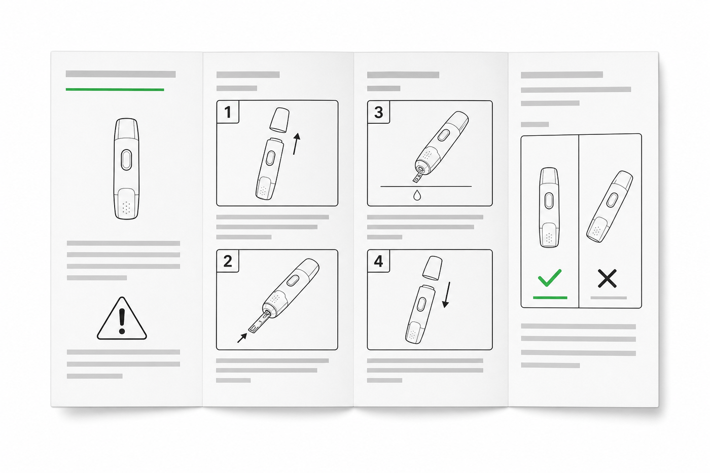
IFU Design Guide: Layout, Symbols & Examples
Practical IFU design guidance for medical devices: page layout, ISO 15223-1 symbols, warning panels, illustrations, and a reusable section template.
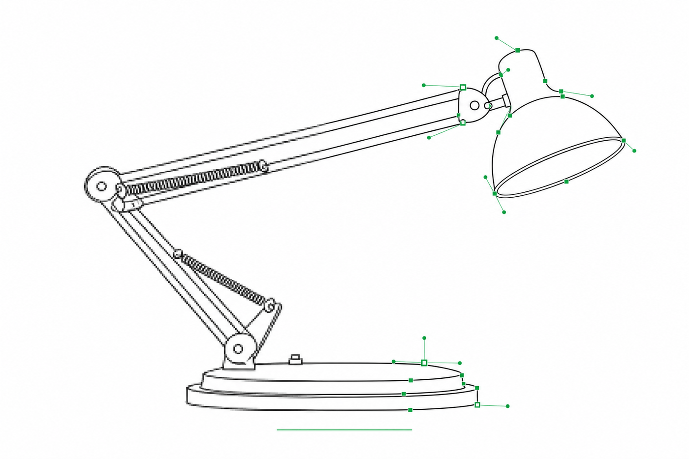
Image to SVG for Illustrator: How to Get Editable Strokes for Technical Line Art
Why many image-to-SVG conversions arrive in Illustrator as filled outlines you can't restyle — and two workflows that produce stroke-based, centerline-style SVG line art with adjustable line weights.

How to Write Work Instructions (Step-by-Step, With Examples)
A practical guide to writing work instructions operators actually follow: the 9-step process, one-action steps, photos vs. illustrations, torque and QC callouts, and a reusable template.