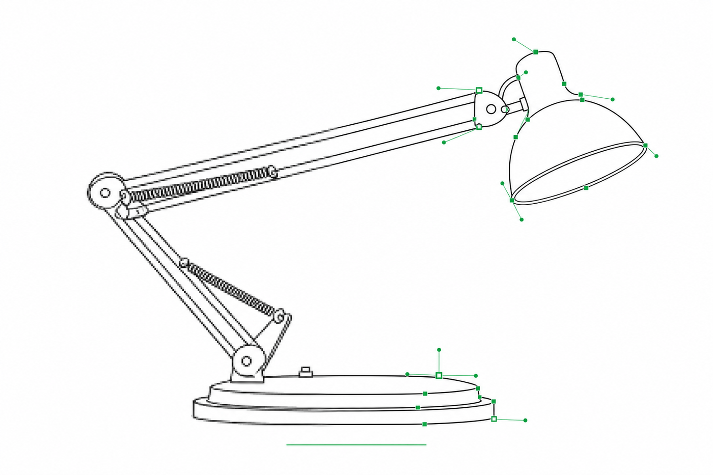
Image to SVG for Illustrator: How to Get Editable Strokes for Technical Line Art
Why many image-to-SVG conversions arrive in Illustrator as filled outlines you can't restyle — and two workflows that produce stroke-based, centerline-style SVG line art with adjustable line weights.
A documentation designer receives a batch of line drawings for a product manual. The client wants one change: make every line slightly heavier so the figures survive newsprint. The files are SVG, so this should be a thirty-second job — select all, bump the stroke weight, done. But when the first file opens in Illustrator, there are no strokes to adjust. Every "line" is actually a thin filled shape: two parallel edges with black between them. Changing the weight means offsetting paths one by one, and the thirty-second job becomes an afternoon.
If you have searched image to SVG and ended up with files like that, the problem is not Illustrator and it is not you. It is how the SVG was traced.
Use ManualFig to generate stroke-based SVG line art directly from a text prompt, or to convert an existing figure — the two workflows this guide compares with real files you can download.
Why some SVGs are still hard to edit in Illustrator
"SVG" only tells you the container. It says nothing about what is inside. Most free image-to-SVG converters — and Illustrator's own default Image Trace — work by finding the edges of dark regions and wrapping each region in a filled path. Adobe's Image Trace documentation describes exactly this: raster art becomes vector shapes. For a logo or a print silhouette that is the right answer.
For technical line art it is the wrong answer. A drawn line, outline-traced, becomes a long thin polygon filled with black. It scales fine, it prints fine — but the one thing you most often need to do to a technical drawing, change the line weight, is no longer a property you can edit. Illustrator users run into this constantly: the community is full of threads asking why a traced drawing came back as outlines instead of paths along the center of each line.
What you actually want for manuals, IFUs, and assembly guides is stroke-based SVG: each visible line is a single path with fill: none and a stroke-width, running along the centerline of the drawn line. Then line weight is one number, and Illustrator can change it globally in one edit.
Fill/outline vs. stroke/centerline, in one look
| Outline-traced SVG | Stroke-based SVG | |
|---|---|---|
| A drawn line becomes | A thin filled polygon (two edges) | One path along the center |
| Line weight lives in | The shape's geometry | The stroke-width property |
| Make all lines heavier | Re-offset every path by hand | Select all → change stroke weight |
| Line caps and joins | Baked into the geometry | stroke-linecap / stroke-linejoin, editable |
| Best for | Logos, silhouettes, laser cutting | Technical line art, manuals, diagrams |
Illustrator's Image Trace does have a Centerline stroke mode, but it is tuned for simple mono-weight artwork, and on a realistic product drawing it tends to fragment curves and merge nearby lines. The more reliable route is to produce stroke-based SVG at generation time instead of repairing it after tracing.
Workflow 1 — simple figures: generate the SVG directly
If the figure is a reasonably simple object — a tool, an appliance panel, a gesture diagram, a single product view — describe it and generate SVG as the native output format. ManualFig sends your prompt to a stroke-native SVG model, so the paths are born as centerline-style strokes rather than traced afterwards.
The desk lamp below was generated directly from this prompt, with SVG selected as the output mode:
A desk lamp with an adjustable two-segment arm, a hinged head, and a round weighted base, shown in three-quarter view as a clean instruction-manual line illustration on a white background. A thin curved arrow indicates the lamp head tilting downward.
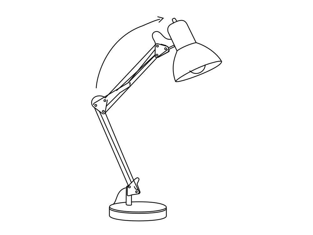
Inside this file (download the SVG, 4.3 KB) there are 38 elements — 28 paths, 7 circles, 2 lines, 1 polyline — and every single one is fill: none with a stroke. The whole drawing uses one effective stroke weight (2.5 on a 1000×750 viewBox), so it opens in Illustrator as a set of clean, uniform strokes.
Workflow 2 — complex figures: generate an image first, then convert
Direct SVG generation has a complexity ceiling. Figures with fine mechanical detail, dense internal structure, or realistic proportions are still easier to get right as a raster image, where the model can draw freely. For those, the better path is two steps: generate (or upload) the raster line art, get it exactly right, then convert it to SVG.
This is the raster lamp we generated first — a normal PNG line drawing:
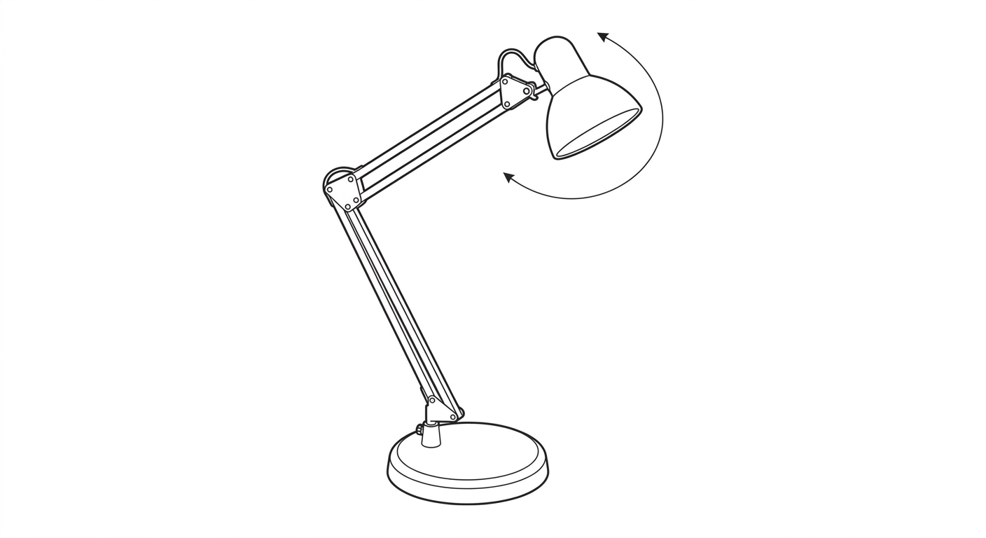
And this is the same image after one-click conversion to SVG in ManualFig:
The converted file (download the SVG, 3.8 KB) contains 33 elements. The line work — arm segments, hinges, base ellipses — is stroke-based, with stroke widths defined once in six CSS classes, so Illustrator can still restyle line weight by class or by selection. Two elements are filled shapes: the solid arrowhead. That is worth being precise about:
The output is editable, stroke-based SVG line art. Main outlines can be adjusted in Illustrator, while some elements such as arrowheads may remain filled shapes.
That trade-off is the honest state of the art. Arrowheads and other deliberately solid marks should stay filled; what matters is that the drawing itself — the lines you will want to restyle — arrives as strokes.
The same lamp, two ways: what actually differs
| Direct SVG generation | Image → SVG conversion | |
|---|---|---|
| Elements | 38, all stroked, zero fills | 33, stroked line work + 2 filled (arrowhead) |
| Stroke weights | One effective weight (2.5) | Six weights (0.20–0.36), grouped in CSS classes |
| Character | Simplified, diagram-like | Faithful to the source image's detail |
| Best when | The figure is simple enough to describe | The figure needs raster-level detail first |
Download both files above and open them side by side in Illustrator — the difference in how they select and restyle tells you more than any screenshot.
Adjusting stroke widths in Illustrator
With stroke-based SVG, the newsprint job from the opening paragraph really is thirty seconds:
- Open the SVG in Illustrator (File → Open, not Place, if you want to edit).
- Select → All, then set a new Stroke weight in the Control or Stroke panel — every stroked path updates at once.
- For selective changes, use Select → Same → Stroke Weight to grab one weight class (hinge details vs. main outlines, for example) and adjust it independently.
- Set Scale Strokes & Effects (Preferences → General) before resizing, so line weights scale — or stay fixed — deliberately rather than by accident.
Because converted files group their weights into a few classes, step 3 works especially well: the six weights in the lamp above behave like six named layers of line hierarchy.
Do you need to remove the background first?
For conversion, a clean white or plain background gives the tracer an unambiguous figure boundary, so line-art images generated by ManualFig convert well as-is. If you are converting a photo or a screenshot with a busy background, convert it to line art first (see our photo to line drawing guide) rather than vectorizing the photo directly — vectorizing photographic shading produces exactly the filled-region soup this article is trying to avoid.
PNG or SVG for the final deliverable?
Short version: PNG when the figure lives at exactly one size in one place; SVG when it will appear at two or more sizes, or when anyone downstream may need to restyle it. Our product line art guide covers the decision in detail. For manuals that ship to print and web, stroke-based SVG is the safer archive format: downgrading to PNG is one export, and the line weights remain one edit away.
Generate your own
Both lamps in this article came out of the same tool with no manual cleanup:
- Open ManualFig and describe your figure — or upload an existing image.
- Choose SVG as the output mode for direct generation, or generate an image and press Convert to SVG on the result.
- Open the exported SVG in Illustrator and restyle the strokes as you need.
If a figure is simple, generate it as SVG directly. If it needs detail, get the image right first and convert. Either way, the lines arrive as lines — not as outlines pretending to be lines.
Related tools: Instruction Manual Generator with Pictures, Photo to Line Drawing for Manuals.
Author

Researcher · University of Arts in Poznan
Davie Chen is a researcher at the Faculty of Animation and Intermedia, University of Arts in Poznan, studying generative AI for scientific figure creation, patent illustration, instruction graphics, and manuscript drafting. ManualFig AI is one of the research-to-product tools built from this work.
View author profileCategories
More Posts

Manufacturing Assembly Instructions: Format, Examples, and How to Illustrate Each Station
What a manufacturing assembly instruction must contain, how to lay out one step per page, three worked station examples (torque, orientation, inspection), and a template you can copy.
IFU Design Guide: Layout, Symbols & Examples
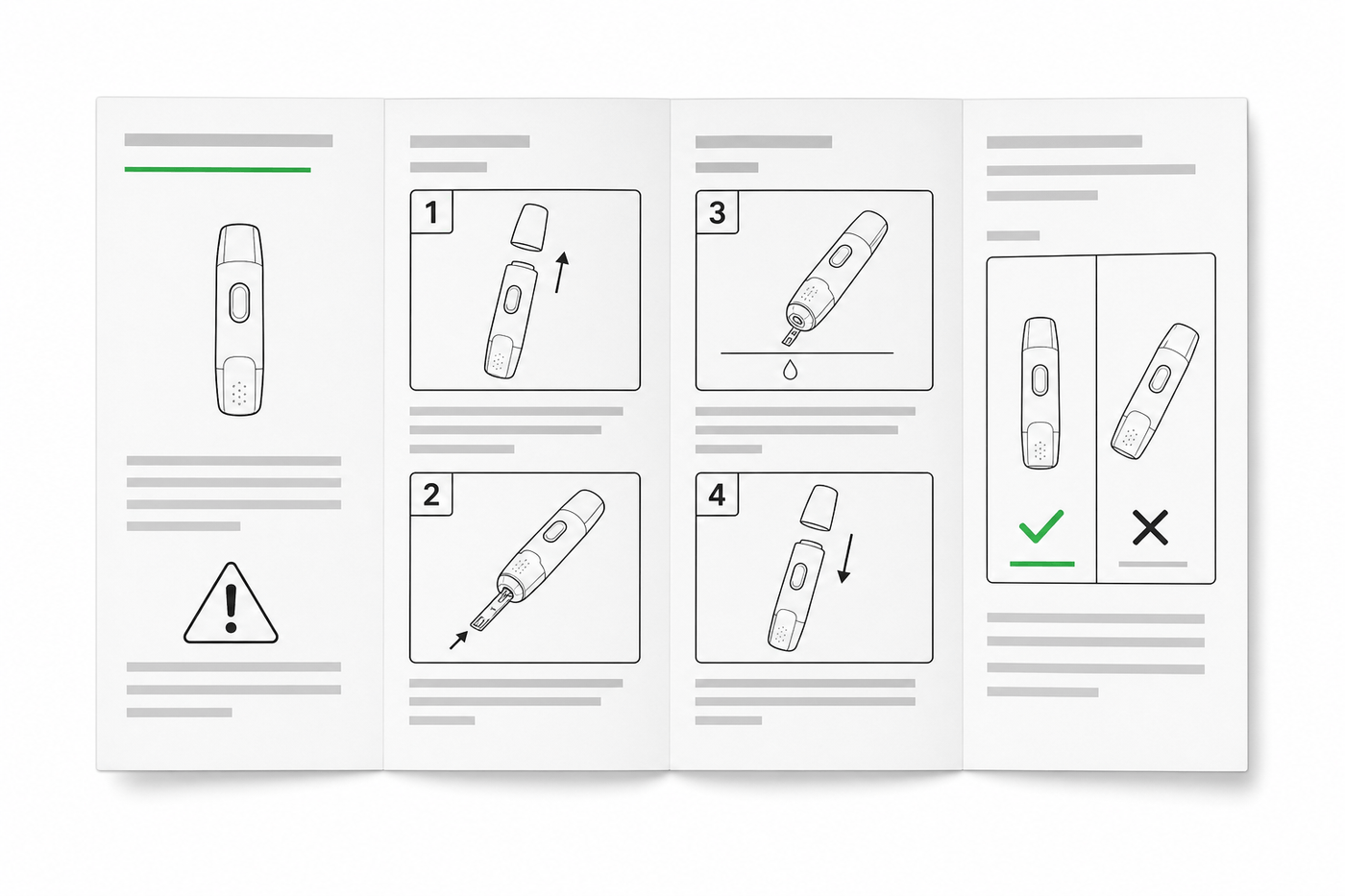
Practical IFU design guidance for medical devices: page layout, ISO 15223-1 symbols, warning panels, illustrations, and a reusable section template.

How to Write Work Instructions (Step-by-Step, With Examples)
A practical guide to writing work instructions operators actually follow: the 9-step process, one-action steps, photos vs. illustrations, torque and QC callouts, and a reusable template.