Installation Guide Illustration Generator
Create installation guide illustrations
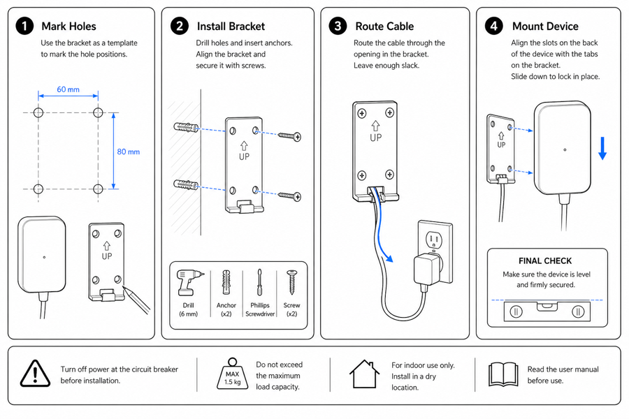
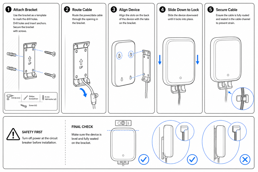
Show mounting, wiring, orientation, fasteners, alignment marks, and final inspection steps.
Installation step
 Example output
Output: manual-ready line art
Installation details that need visuals
Use diagrams where text alone leaves room for reversed parts, wrong holes, or skipped inspection.
Mounting and alignment
Show holes, brackets, wall anchors, level marks, spacing, orientation, and surface relation.
Wiring and routing
Illustrate cable paths, polarity, connector orientation, bend limits, and safe routing.
Final verification
Show lock state, tension, clearance, leak checks, power-on confirmation, or stability checks.
Input → manual line art → editable export
Generate a first draft in the tool above, then open /generate to select the image, keep editing, make new versions, and export.
From product reference to manual-ready output
ManualFig keeps the prompt, uploaded references, generated options, revisions, and exports in one browser workflow.
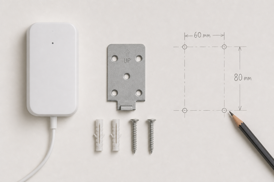
Upload or describe the product
Start from a product photo, CAD screenshot, sketch, existing manual page, or a short step list.
Generate the instruction visual
Create line art, numbered panels, arrows, callouts, detail views, warnings, and completion checks.
Refine and export
Select a result, revise it with text, keep versions together, and export PNG or SVG for documentation.
Related ManualFig pages
ManualFig converts installation notes and product references into visual setup guides that reduce orientation mistakes and missed checks.
Installation Guide Illustration FAQ
Can ManualFig create installation guide illustrations?
Yes. It can generate visuals for mounting, wiring, orientation, alignment, fasteners, and final verification.
Can I use photos or CAD screenshots?
Yes. Product photos, CAD screenshots, sketches, and existing manual pages can guide the generated illustration.
What is the difference between installation and assembly?
Installation usually fits a product into an environment. Assembly builds the product from parts. ManualFig supports both workflows.
Can I add safety instructions?
Yes. Ask for warning cues, forbidden actions, correct/incorrect states, lock checks, and final inspection steps.
Generate an installation guide visual
Describe the installation step, add product references, and create manual-ready diagrams.