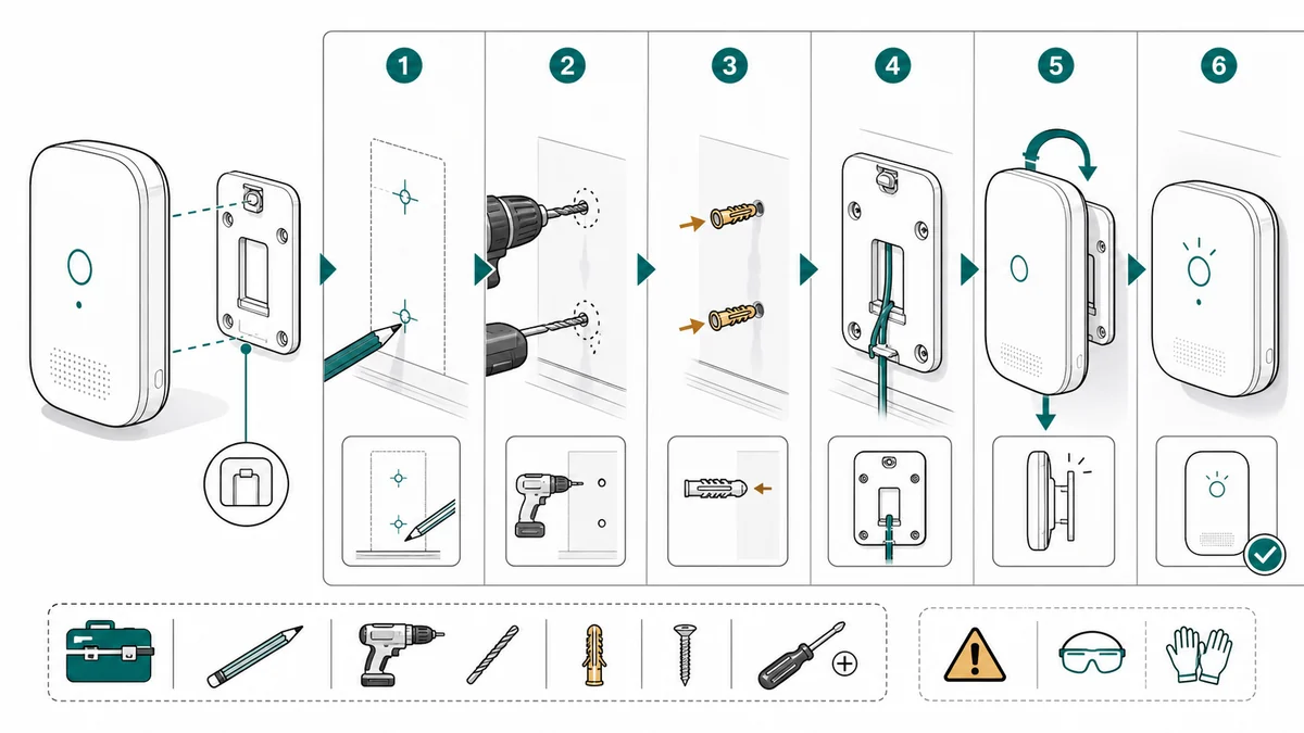
Installation Guide Illustrations for Hardware and Electronics
How to create installation guide illustrations for mounting, wiring, alignment, fasteners, cable routing, safety cues, and final checks.
Installation guides are different from assembly guides. Assembly builds the product from parts. Installation puts the product into an environment: a wall, cabinet, vehicle, network rack, appliance bay, or desk setup.
That environment creates the main visual problem. Users need to see orientation, mounting surface, cable path, clearance, and final checks.
Use the Installation Guide Illustration Generator for focused installation pages.
Common mistakes to avoid
Installation drawings often fail because they show the product clearly but not the environment. The reader can identify the device, but still does not know which side faces up, where the cable exits, how much clearance is needed, or what "fully seated" looks like.
Avoid these mistakes:
- Showing a floating product with no wall, bracket, cabinet, rack, or mounting surface
- Omitting hole spacing, bracket orientation, cable route, or connector direction
- Treating "attach" as one action when the real workflow includes mark, drill, anchor, route, mount, and test
- Showing only the tool and not the contact point
- Hiding safety steps such as power off, depressurize, cool down, or lockout
- Forgetting the final state: level, clicked, sealed, powered, paired, or ready
Installation art should answer both questions at once: where does it go, and how does the user know it is installed correctly?
What to show
Strong installation visuals usually include:
- Mounting direction
- Hole or bracket alignment
- Cable routing
- Connector orientation
- Tool and fastener use
- Safety or power-off cues
- Final inspection state
If a step can be installed backward, upside down, or into the wrong port, draw it.
The environment does not need to be photorealistic. A simple wall plane, cabinet outline, rack rail, appliance bay, or desktop edge is enough to anchor the action.
Break the installation into visual decisions
Most installation guides include more decisions than teams expect. Before generating images, list the decisions a reader has to make:
- Which surface or opening is valid?
- Which orientation is correct?
- Which holes, brackets, rails, or tabs align?
- Where does the cable, hose, gasket, or antenna go?
- Which connector or port is used?
- What tool or fastener is required?
- What must be checked before power is restored?
Each decision can become a panel, a callout, or a correct/incorrect comparison. If a decision is likely to cause a support ticket, make it visible.
Prompt templates
Create a three-panel installation guide illustration for a wall-mounted sensor.
Panel 1: mark the mounting bracket orientation on the wall.
Panel 2: route the cable through the lower channel without pinching it.
Panel 3: attach the sensor until it clicks and show a green final check.
Use clean technical line art, white background, arrows, callouts, and one warning cue.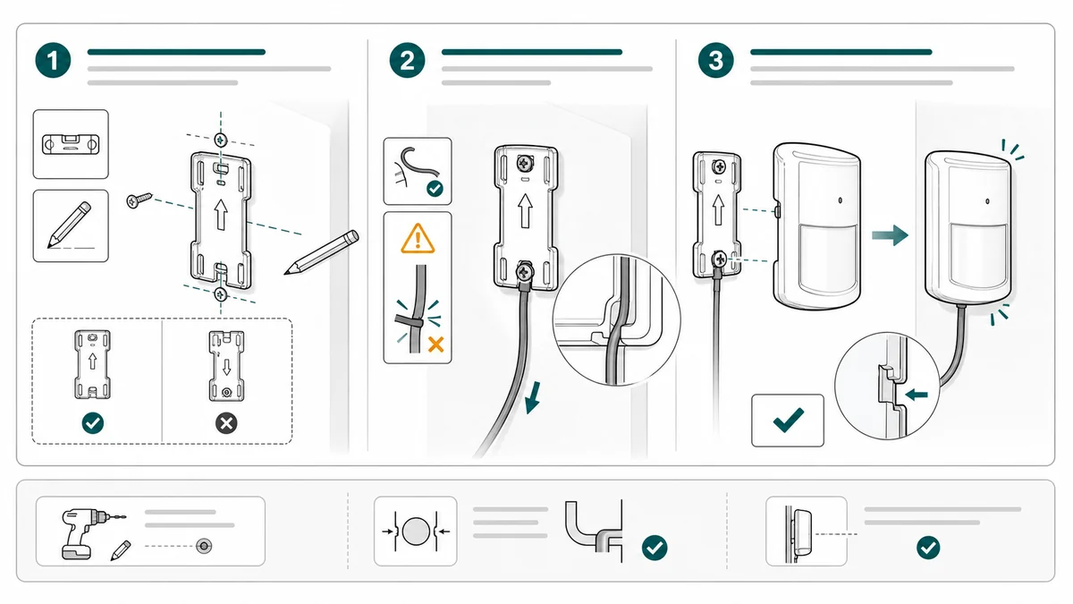
For a cable or connector installation, be more specific:
Create a four-panel installation illustration for connecting a control module.
Panel 1: power off the device before opening the access cover.
Panel 2: align the keyed connector with the matching port.
Panel 3: push straight until the latch clicks, with a close-up on the latch.
Panel 4: route the cable through the side channel and close the cover.
Use clean manual line art, blue arrows, one amber caution icon, and no brand logos.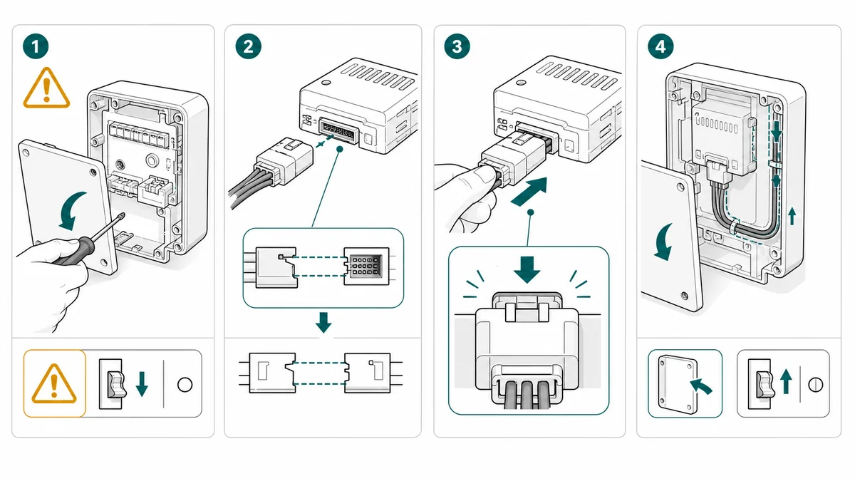
For a wall or cabinet mount, show the surface:
Create an installation guide figure for mounting a small device inside a cabinet.
Show the cabinet wall, bracket, two screws, and cable clearance area.
Include a correct/incorrect comparison for bracket orientation.
Use simple line art, leader lines, large arrows, and a final level check.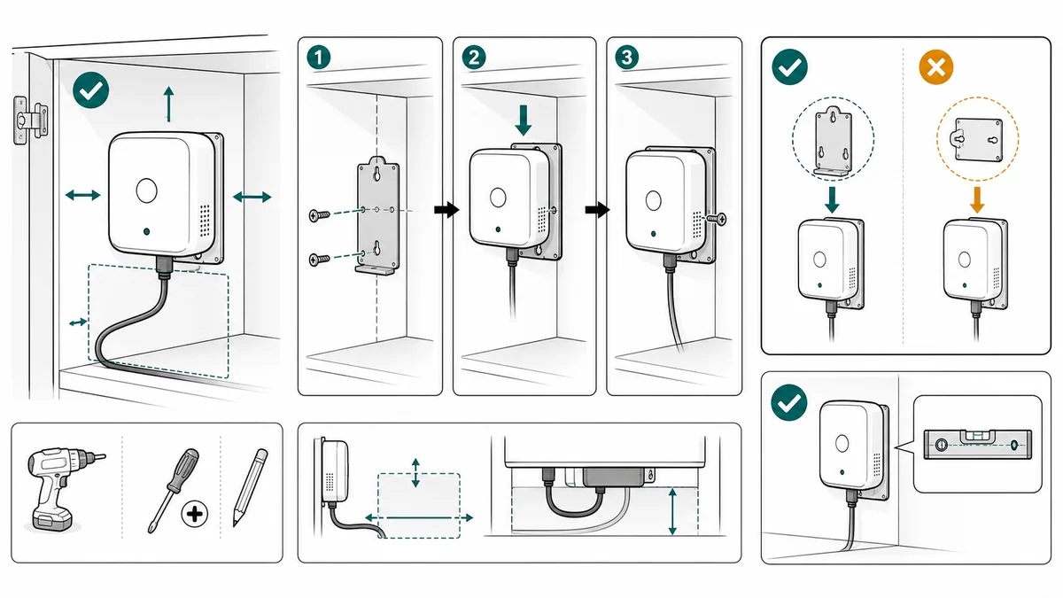
Add correct and incorrect states
Installation errors often look almost right. A correct/incorrect pair helps users compare:
- Connector seated vs loose
- Cable routed through channel vs pinched
- Bracket level vs tilted
- Lock engaged vs open
- Seal aligned vs twisted
ManualFig can draft these pairs as manual panels, then you can revise individual outputs before export.
Correct/incorrect panels are especially useful when support agents repeatedly ask customers for photos. If the support team can say "match the picture on the left," the manual is doing real operational work.
A practical ManualFig workflow
Use ManualFig as the drafting layer between raw product references and the final installation page.
- Upload a product photo, bracket photo, CAD screenshot, or existing installation draft.
- Describe the installation environment: wall, cabinet, rack, appliance bay, vehicle interior, countertop, or enclosure.
- Write the steps as separate actions: mark, drill, anchor, align, route, connect, mount, secure, test.
- Add safety requirements and final checks.
- Generate the panel set.
- Revise individual panels for orientation, cable path, and final state.
- Export PNG for help center pages or SVG for print and layout tools.
The key is to tell the model what must not change. If the cable exits from the lower-right channel, say that. If the bracket notch must face upward, say that. Installation drawings are only useful when these constraints survive generation.
Review boundary
Installation visuals can affect safety, warranty, and product support. Use AI output as a drafting accelerator, then route final diagrams through product, engineering, support, or compliance review where needed.
Before publishing, check:
- Does the image show the installation surface or environment?
- Are orientation cues visible before the user commits to drilling, cutting, or routing?
- Are cable, hose, seal, or connector paths unambiguous?
- Is the required tool shown near the step where it is used?
- Is the safety state shown before the risky action?
- Does the final panel show the correct installed state?
- Are any dimensions, ratings, or certification marks approved rather than invented?
Related workflows: Safety Instruction Illustration Generator, Work Instruction Illustration Generator, and Product Photo to Manual Illustration.
Author

Researcher · University of Arts in Poznan
Davie Chen is a researcher at the Faculty of Animation and Intermedia, University of Arts in Poznan, studying generative AI for scientific figure creation, patent illustration, instruction graphics, and manuscript drafting. ManualFig AI is one of the research-to-product tools built from this work.
View author profileCategories
More Posts
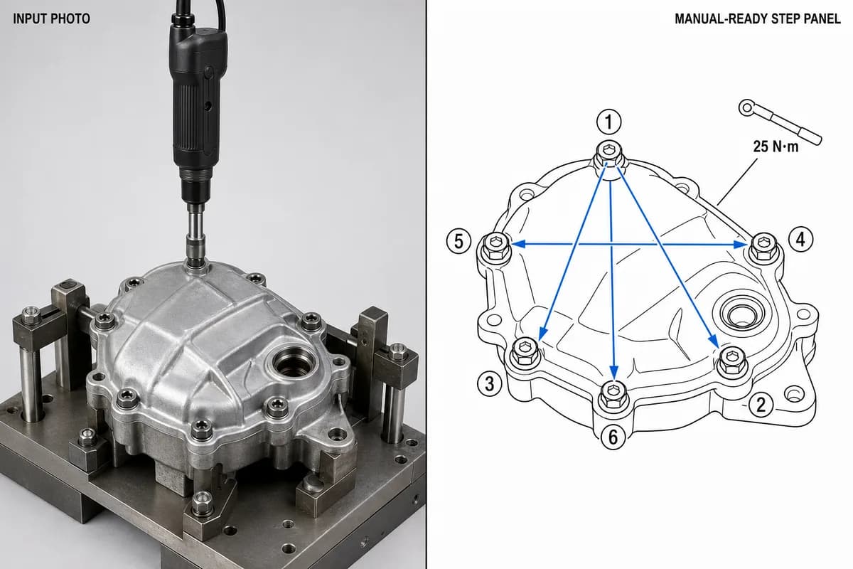
Manufacturing Assembly Instructions: Format, Examples, and How to Illustrate Each Station
What a manufacturing assembly instruction must contain, how to lay out one step per page, three worked station examples (torque, orientation, inspection), and a template you can copy.
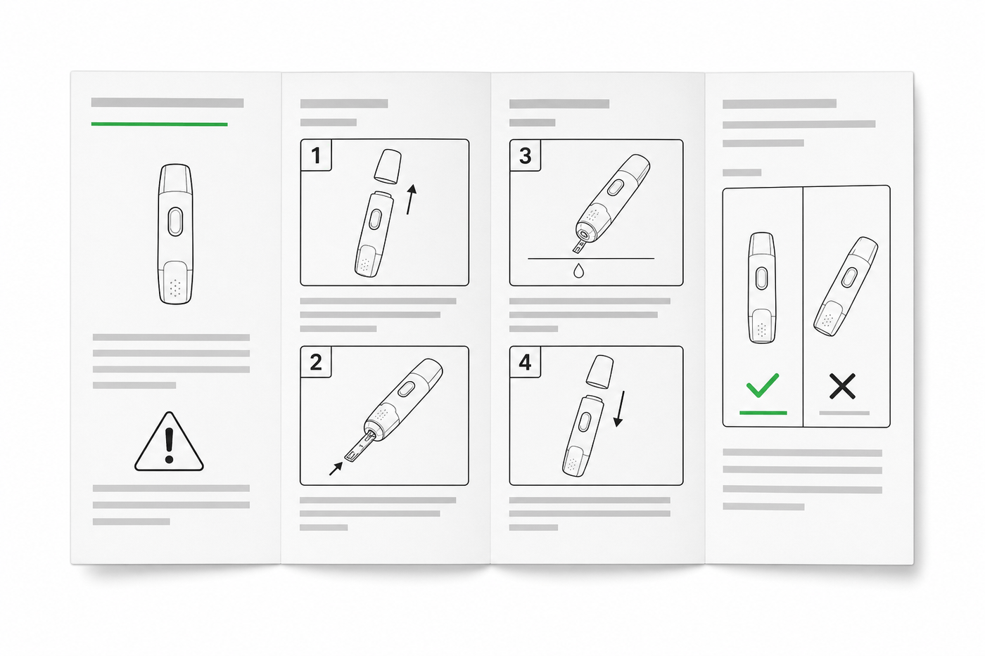
IFU Design Guide: Layout, Symbols & Examples
Practical IFU design guidance for medical devices: page layout, ISO 15223-1 symbols, warning panels, illustrations, and a reusable section template.
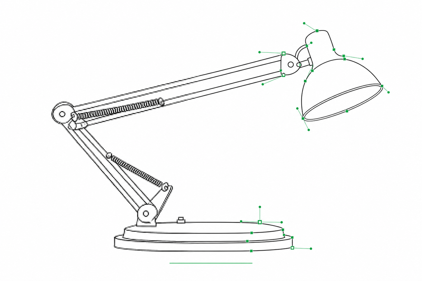
Image to SVG for Illustrator: How to Get Editable Strokes for Technical Line Art
Why many image-to-SVG conversions arrive in Illustrator as filled outlines you can't restyle — and two workflows that produce stroke-based, centerline-style SVG line art with adjustable line weights.