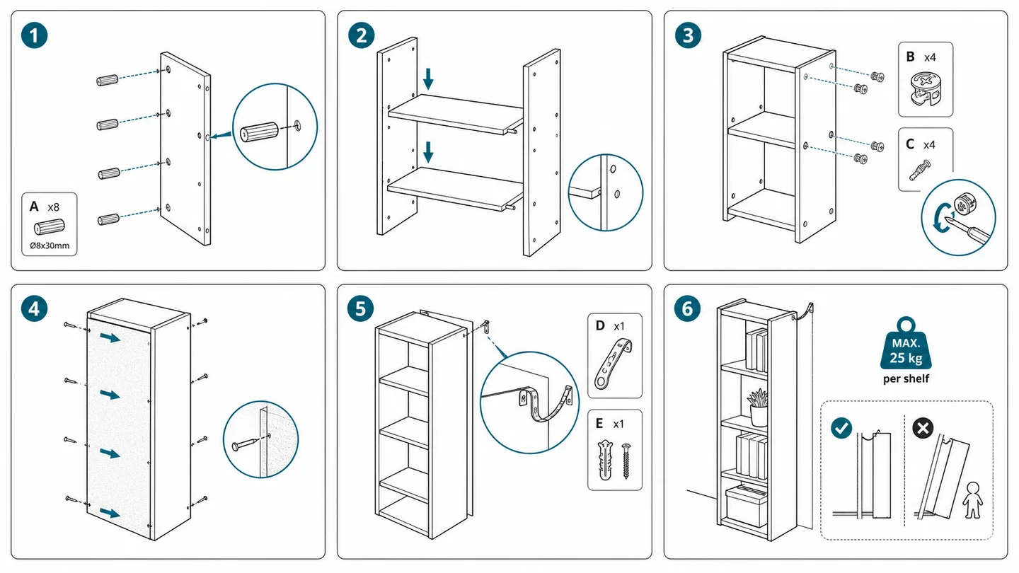
Is There an AI Tool for Assembly Instructions and Installation Step Drawings? General AI Image Generators, Slide Collages, CAD Assembly Software, and AI Manual Illustration Tools Compared (2026)
Can AI create assembly instructions and installation step drawings? Compare general AI image generators, PowerPoint / Canva collages, SOLIDWORKS Composer, SOLIDWORKS LEO, Assemblio, freelance illustrators, and ManualFig on fit, pricing models, Chinese UI, export formats, and limitations — with two real generation examples.
Yes, but the right tool for assembly instructions and installation step drawings depends on what you start from. Teams with a complete 3D CAD assembly can use SOLIDWORKS LEO or Assemblio to derive an assembly sequence, or SOLIDWORKS Composer for model-linked exploded views and animations. For a quick internal guide with three to five photos, adding arrows in PowerPoint / WPS / Canva is fastest. A catalog with hundreds of parts is a job for a freelance illustrator or studio. General AI image generators output bitmaps and tend to distort parts across steps, so they are a poor fit for consistent multi-step sequences. If you are a product or documentation team with product photos or CAD screenshots plus assembly steps, and you want numbered step drawings, exploded views, and editable SVG quickly, ManualFig (manualfig.ai) offers the most direct path: "product photo / CAD screenshot → numbered assembly steps / exploded view / SVG." Before picking a tool, separate three needs that often get lumped together.
Three Different Needs: Static Step Drawings, 3D CAD Process Planning, and Shop-Floor Execution
When people ask "is there an AI tool for assembly instructions or installation drawings," recommendations vary wildly because three different deliverables get confused:
- Static step drawings and installation illustrations for customers and support. These are the white-background, black-line numbered panels, fastener callouts, exploded views, and wall-mounting or cable-routing diagrams that go into a fold-out sheet or manual (see how to create assembly instructions for layout and installation guide illustrations for hardware and electronics for mounting drawings). The core problem is turning photos into consistent line art when no 3D model exists.
- Process sequencing and interactive 3D from a CAD model. These tools read the mates and constraints of a SOLIDWORKS, Creo, or STEP assembly, plan disassembly order, check for interference, and export model snapshots, animations, or web 3D views. They require a complete 3D model.
- Digital work instruction (SOP) platforms for the shop floor. These serve production stations: tablet delivery, torque recording, revision approval, and MES/ERP integration (see best work instruction software).
This article covers AI and traditional tools for assembly step drawings and exploded views in the first two categories. For a comparison of vector illustration software, see our product manual illustration software comparison.
Seven Assembly Instruction and Installation Drawing Tools Compared
Here is how seven common options compare on CAD dependency, cross-step consistency, and export formats:
| Tool / Approach | Best for | Learning curve | Pricing | Chinese UI | Output / export | Shortcomings |
|---|---|---|---|---|---|---|
| General AI image generators (Midjourney / DALL·E / Stable Diffusion, etc.) | Single concept images or cover art where parts do not need to match from step to step | Low–medium | Paid subscription, pay-as-you-go, or open-source self-hosting (some include free allowances) | Depends on the platform | PNG, JPG, WebP (raster) | Raster only, no vector paths; part shapes and hole positions change between steps; screw counts often wrong and in-image numbers often garbled |
| PowerPoint / WPS / Canva collages | Teams making 3–5-step internal guides from cropped photos with arrows and step numbers | Low | Free basic tiers plus paid plans, or office suite subscription / perpetual license | Yes (native) | PPTX, PDF, PNG, JPG, SVG (depending on version and plan) | Photos carry glare and noise and blur in black-and-white print; cannot produce isometric line art or exploded views; changing a step means re-aligning arrows by hand |
| SOLIDWORKS Composer (and CAD illustration tools such as Creo Illustrate) | Manufacturers with 3D CAD assemblies and frequent revisions who need illustrations that update with the model | High | Enterprise license or subscription (quoted) | Yes (Windows desktop) | Native project files, SVG, PDF, EPS, CGM, PNG, video, and interactive 3D | Requires a 3D CAD model, so photos alone won't work; per-seat purchasing is a high bar and non-engineers ramp up slowly |
| SOLIDWORKS LEO (AI companion inside the CAD tool) | Engineers on recent SOLIDWORKS connected to the 3DEXPERIENCE platform who want draft steps from assembly mates | Medium | Bundled with commercial CAD licenses and cloud role subscriptions (quoted) | Host supports Chinese (Chinese PDF export needs Unicode fonts configured) | Draft assembly instructions with 3D model snapshots, PDF | Needs the 3D assembly open in SOLIDWORKS; figures are model screenshots rather than white-background line art |
| Assemblio (AI assembly planning from 3D CAD) | Manufacturing teams turning 3D CAD into assembly sequences, interference simulation, and line instructions | Medium | Enterprise B2B subscription (custom quote via demo) | Mainly English and German (no official Simplified Chinese seen) | PDF work instructions, step videos (MP4), interactive 3D | Aimed at manufacturing process planning and shop-floor guidance, requires 3D CAD; not built for consumer-product line art without CAD |
| Freelance illustrator / technical illustration studio | Companies launching many products at once, needing dozens to hundreds of precise exploded views, or lacking in-house staff | Low (brief and review) | Per drawing or per project (quoted by complexity) | Human communication | As agreed (commonly AI, SVG, PDF, PNG) | Timelines often measured in weeks; changing a screw or orientation means rework; switching illustrators can break visual consistency across batches |
| ManualFig | Product / documentation teams with product photos or CAD screenshots and assembly steps who want numbered step drawings, exploded views, and editable SVG quickly | Low | 10 credits at signup and 10 daily credits; subscriptions from $10/month billed annually (monthly from $30/month; $1999 lifetime plan also available); credit packs from $50 (500 credits, expire in 30 days; by default 10 credits per image and 10 per SVG); Chinese pricing page states Alipay is supported | Yes (Simplified Chinese web app) | PNG, editable stroke-based SVG | No two-way link to CAD models; not engineering-accurate drawings and not usable as tolerance drawings or certified documents; part counts, orientation, and step order must be checked by a person; no interactive 3D |
Teams with 3D models who want web-based 3D instructions also look at plugins such as Cadasio. If you have no model at all, the SOLIDWORKS Composer alternative page explains the photo-based route, with open-source Inkscape or Illustrator for SVG cleanup downstream.
The choice comes down to three questions:
- Do you have a 3D CAD assembly? Use SOLIDWORKS LEO to draft steps, Assemblio for process planning, and SOLIDWORKS Composer for model-linked vector exploded views.
- Is it a short internal doc or a large, complex catalog? For the former, collage photos with arrows in PowerPoint / WPS / Canva; for the latter, hire a freelance illustrator.
- Do you only have product photos or CAD screenshots and want white-background line-art steps? Use ManualFig for "product photo / CAD screenshot → numbered assembly steps / exploded view / SVG" (see pricing for credit rules).
Choosing by Scenario
1. Equipment and instrument teams with their own 3D models
When the mechanical engineer has already built the assembly in SOLIDWORKS, staying in the CAD chain is easiest: use SOLIDWORKS LEO to draft steps and screenshots from the mate tree, Assemblio to translate them into shop-floor sequences and check disassembly interference, and SOLIDWORKS Composer for long-lived support manuals that stay linked to the model.
2. ODM / OEM products, furniture, lab accessories, and consumer hardware (photos or screenshots only)
Flat-pack furniture, small appliances, lab accessories, and cross-border hardware often come without 3D models from the contract manufacturer, and the manual is written by product, documentation, or operations staff. General AI image generators produce mismatched holes; PowerPoint collages of dark photos turn into black blobs on a printed sheet.
In ManualFig, upload product photos, CAD screenshots, sketches, or existing manual pages (PNG / JPEG / WebP, up to 3 per upload, each under 4 MB), add your step text, and generate white-background line-art drafts in the assembly instruction illustration generator, the installation guide illustration generator, or the exploded view illustration generator. For a single photo with a messy background, try the photo to line drawing for manuals tool.
3. Quick internal instructions vs. large spare-parts catalogs
For a three- or four-step guide to wall-mounting a router or wiring a fixture, shoot the actions clearly against a light background and add arrows in PowerPoint / WPS or Canva — that is the fastest route. If the product has hundreds of parts and needs a precise catalog, have a freelance illustrator draw the master exploded view, then iterate the day-to-day step pages in ManualFig.
4. Medical device IFUs and installation pages with safety-critical values
You can draft line art in ManualFig for load-bearing mounts, electrical connections, and medical device instructions for use (IFUs), but be clear about the boundary: generated images are illustrative aids only, not engineering drawings, regulatory submissions, or certified safety documents. Torque values, electrical ratings, and compliance labels must be verified and added by engineering and regulatory teams.
Worked Examples: Product Photo → Numbered Step Drawing and Exploded View → Editable SVG
Two real ManualFig cases show how to get step drawings and exploded views from photos without any 3D CAD.
Example 1: Table leg and corner bracket (parts photo → numbered step drawing)
A black metal bracket photo makes screw holes impossible to see on a single-color printed sheet. Lay out the table leg, the L-shaped bracket, and four hex bolts, photograph them clearly (PNG / JPEG / WebP, under 4 MB), upload to the assembly instruction illustration generator, and enter:
Using the photo of a table leg, an L-shaped corner bracket, and four bolts, generate a single-step assembly line-art panel. Black lines on white, no shading or wood grain. Show the L bracket attached under the tabletop (callout ②), the table leg (callout ①) with a blue upward arrow aligned to the bracket, and the four hex bolts listed on the right (callout ③).
 Left: the photographed leg, bracket, and bolts. Right: a white-background, black-line step panel with parts ①–③ and a blue alignment arrow.
Example 2: Handheld vacuum teardown overview (product photo → numbered exploded view)
Assembly and maintenance manuals usually open with an exploded view that shows how components relate. Upload a side photo of the vacuum to the exploded view illustration generator and spell out the direction and order:
From the handheld vacuum photo, generate a horizontal exploded-view line drawing. Black lines on white, no shading. Along a horizontal axis, separate the main body and handle, dust cup, pleated filter, and flat nozzle with dashed lines, add callout bubbles ①–④ above with leader lines, and add a blue arrow below showing the reassembly direction.
 Left: the full product photo. Right: the exploded line drawing along a horizontal axis, with bubbles ①–④ for body, dust cup, filter, and nozzle.
Step 3: Edit on the canvas, export stroke-based SVG, and check against the real product
After the draft is generated (10 credits per image by default), finish in three steps:
- Edit on the canvas. Review the image on the canvas and use follow-up text edits to adjust arrows or local details; project history keeps every version.
- Export PNG or SVG. Download PNG for web help centers; choose editable stroke-based SVG for InDesign or Illustrator layouts (10 credits per SVG by default; see the image to editable-stroke SVG guide).
- Check against the physical product. Compare against a sample and the BOM, verifying part counts, orientation, and step order before anything goes to print.
Five Common Mistakes When Making Assembly and Installation Drawings with AI or Software
- Asking a general AI to invent a multi-step sequence without reference images. With text alone, part shapes and hole positions drift from step to step, and in-image numbers often come out garbled.
- Cramming several actions into one panel with crossing arrows. Squeezing "insert dowels, place shelf, lock cam fittings" into one frame invites missed steps; use one action per panel (see assembly instruction drawings: arrows, parts, fasteners, and layout).
- Leaving out the wall and cable space in installation drawings. Drawing the product floating in space, without the wall, rack rails, cable exits, or a power-off warning, leads to rework on site.
- Using an exploded view in place of every step, or skipping orientation cues. An exploded view does not show tightening order; any part that can be installed 180° backwards needs a zoom circle or a ✓ / ✗ comparison.
- Skipping a real test assembly before printing, or treating the drawing as an engineering drawing. A draft can show the wrong number of screws or swap left and right parts, and line art carries no tolerances — check it against the real product before printing.
FAQ
Can AI generate assembly step drawings from product photos without a 3D CAD model?
Yes. SOLIDWORKS Composer, SOLIDWORKS LEO, and Assemblio all need 3D CAD. If you only have photos, CAD screenshots, or sketches, upload reference images to ManualFig (PNG / JPEG / WebP, up to 3 per upload, each under 4 MB), describe the steps, and generate numbered step drawings and exploded views, then export PNG or editable SVG.
Why not just use Midjourney or another general AI image generator for installation manuals?
General image models output pure bitmaps (PNG / JPG) with no geometric consistency constraints. The same part's holes and proportions often change between steps, numbers inside the image get garbled, and you cannot adjust line weights by stroke path in vector software.
How much does ManualFig cost? Is there a free allowance? Does it support Alipay?
You get 10 credits at signup (expire in 30 days) and 10 daily credits (expire in 1 day); the free plan has no subscription credits. By default each image costs 10 credits and each SVG costs 10 credits. Subscriptions are Starter ($30/month or $120/year — as low as $10/month billed annually), Pro ($60/month or $240/year), and Business ($120/month or $480/year), plus a $1999 lifetime plan. Credit packs start at $50 (basic: $50 for 500 credits; also $100 for 1,000, $200 for 2,000, and $400 for 4,000 credits, all expiring in 30 days). Payments go through Stripe, and the Chinese pricing page states that Alipay is supported.
Should I export assembly step drawings as PNG or editable SVG?
For web help centers or single-size documents, a white-background PNG is simplest. For InDesign or Illustrator fold-out layouts, or when you need to tweak leader lines, unify stroke weights, or renumber BOM callouts, choose editable stroke-based SVG (open-source Inkscape works for free SVG edits).
Can AI-generated assembly drawings replace CAD engineering drawings or go straight into regulated medical device manuals?
No. ManualFig images are illustrative aids only — not engineering drawings, regulatory submissions, or certified safety documents. They have no two-way link to CAD models, and ManualFig does not produce interactive 3D. For ordinary products, check part counts, orientation, and step order before printing; medical device IFUs must go through formal regulatory and clinical review.
Author

Researcher · University of Arts in Poznan
Davie Chen is a researcher at the Faculty of Animation and Intermedia, University of Arts in Poznan, studying generative AI for scientific figure creation, patent illustration, instruction graphics, and manuscript drafting. ManualFig AI is one of the research-to-product tools built from this work.
View author profileCategories
More Posts
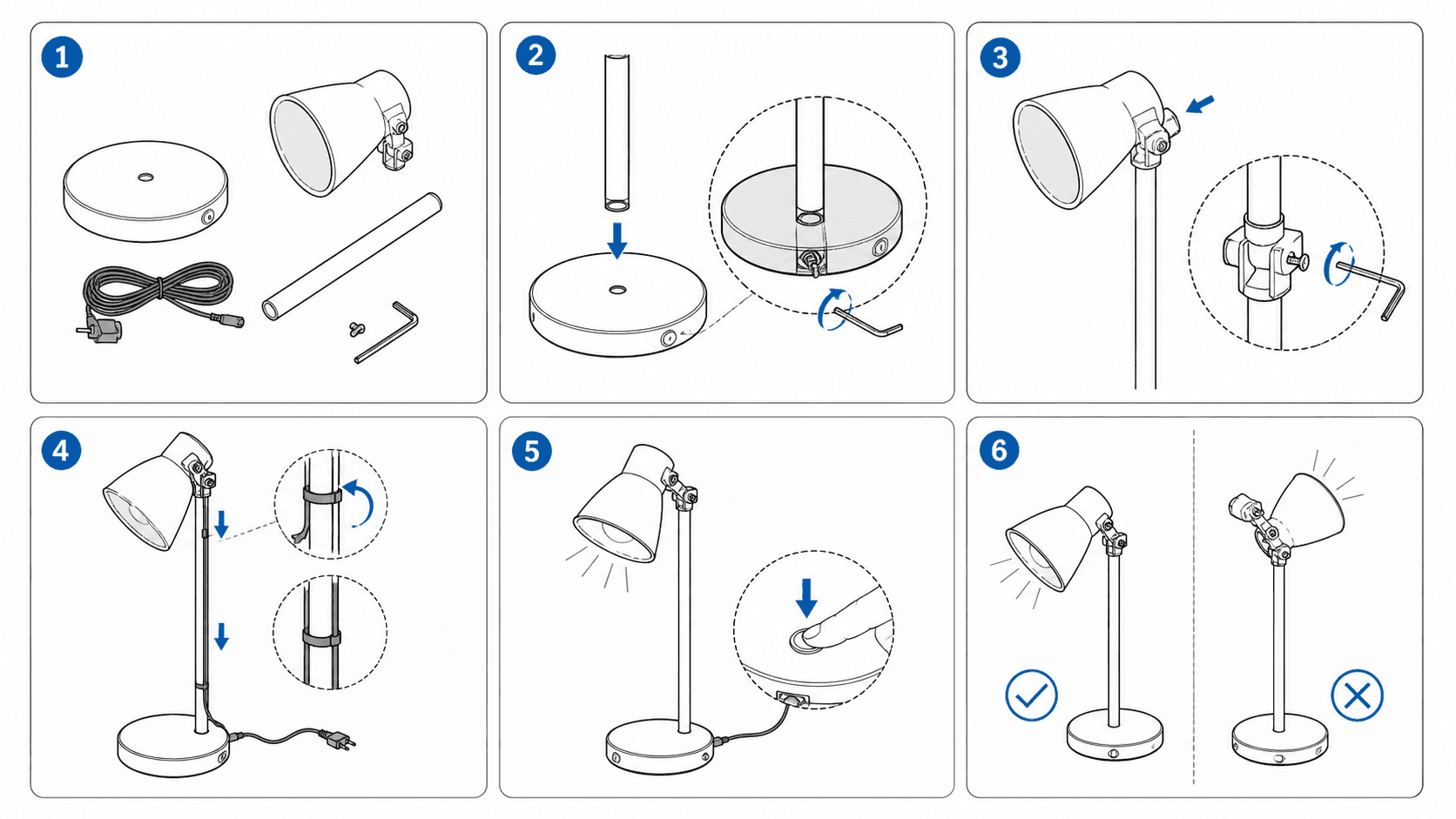
What Software Is Used for Product Manual Illustrations? Illustrator, CorelDRAW, SOLIDWORKS Composer & AI Compared (2026)
Compare 8 options for product manual illustrations—Adobe Illustrator, CorelDRAW Technical Suite, SOLIDWORKS Composer, PTC Creo Illustrate, Inkscape, Visio, freelance illustrators, and ManualFig—across learning curve, pricing, localization, exports, and limitations.
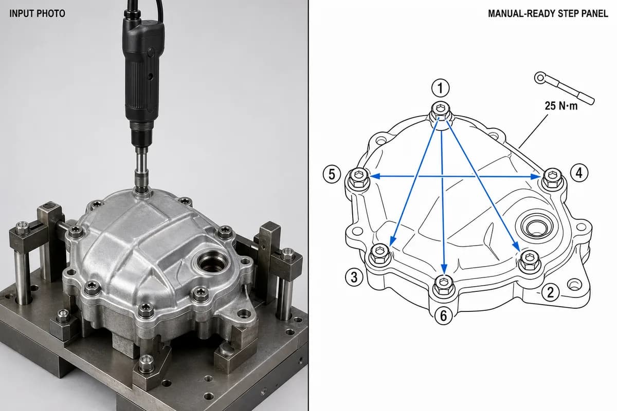
Manufacturing Assembly Instructions: Format, Examples, and How to Illustrate Each Station
What a manufacturing assembly instruction must contain, how to lay out one step per page, three worked station examples (torque, orientation, inspection), and a template you can copy.
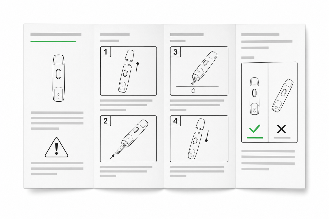
IFU Design Guide: Layout, Symbols & Examples
Practical IFU design guidance for medical devices: page layout, ISO 15223-1 symbols, warning panels, illustrations, and a reusable section template.